PT-120-B-C11-EPA Luminus Devices, PT-120-B-C11-EPA Datasheet
PT-120-B-C11-EPA
Specifications of PT-120-B-C11-EPA
Available stocks


Related parts for PT-120-B-C11-EPA


PT-120-B-C11-EPA Summary of contents
Page 1
... Electronic control of color points and light intensity on a frame by frame basis PhlatLight products benefit from numerous innovations in the domain of packaging, thermal management and optical cou- pling that allow designers to achieve efficient light engine de- signs and deliver high screen brightness. Angular Intensity Distribution- Example 1 ...
Page 2
... PT120 Summary Datasheet - Revision 07 Optical and Electrical Characteristics Bin Kit Emitting Area Emitting Area Dimensions Characteristics at recommended Pulsed Drive Current I 4 Reference Duty Cycle 5 Recommended Peak Drive Current 6 Peak Luminous Flux Peak Radiometric Power Dominant Wavelength FWHM - Spectral bandwidth at 50% of Φ ...
Page 3
... PT120 Summary Datasheet - Revision 07 Optical and Electrical Characteristics Characteristics at Reference Continuous Drive Current I Reference Drive Current Luminous Flux Radiometric Flux Dominant Wavelength 7,8 Color Saturation FWHM - Spectral bandwidth at 50% of Φ 7,8 Chromaticity Coordinates Forward Voltage Dynamic Resistance Note 1: EP-Blue is recommended for new designs. Please see page 9 for part ordering numbers. ...
Page 4
... PT120 Summary Datasheet - Revision 07 Absolute Maximum Ratings 1,2 Maximum Current Maximum Operating Junction Temperature Storage Temperature Range Note 1: Luminus PhlatLight LEDs are designed for operation to an absolute maximum forward drive current density of 2.5A/mm 2 3A/mm pulsed (f>240Hz, duty cycle < 60%). Please refer to absolute maximum rating table above for specific absolute maximum cur- rents for the products covered in this datasheet ...
Page 5
... PT120 Summary Datasheet - Revision 07 Luminous Flux variation with Drive Current - Φ 2000 1500 1000 500 (A) F See notes 1,2 on page 6. Dominant Wavelength variation with Forward Current - λ 635 630 625 620 615 (A) F See notes 1,2 on page 6. Forward Voltage variation with Drive current - V 3 ...
Page 6
... Note 1: For Pulsed operation, typical RGB duty cycles used are 25%, 50% and 25% respectively for pulsed operation (T Note 2: Yellow square indicate device operating point under recommended conditions listed in the Optical and Electrical Char- acteristics table. Note 3: Typical Spectrum at recommended peak drive current. ...
Page 7
... PT120 Summary Datasheet - Revision 07 Thermal Resistance definition = 3 mm from core-board hs Thermistor Information The thermistor used in PhlatLight™ devices mounted on core-boards is from Murata Manufacturing Co. The global part number is NCP15XH103J03RC. Please see http://www.murata.com/ or http://www.murata.co.jp for details on calculating thermistor tempera- ture. Electrical Pinout ...
Page 8
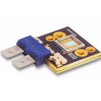
... TOP OF METAL SUBSTRATE TO EMITTING AREA Recommended connector for Anode and Cathode: Panduit Disco Lok Thermistor Connector: MOLEX P/N 53780-0270. Recommended Female: MOLEX P/N 51146-0200 or equivalent For detailed drawing of the PT120 Type CX package, please refer to the DWG-001124 document DIMENSIONS IN MILLIMETERS 2.60 EMITTING ...
Page 9
... Red PT-120-G-C11-MPB Green 1 PT-120-B-C11-MPB Blue 2 PT-120-B-C11-EPA EP-Blue Note 1: Not recommended for new designs Note 2: Bin Kit EPA Blue is recommended for new designs. The products, their specifications and other information appearing in this document are subject to change by Luminus Devices without notice. Luminus Devices assumes no liability for errors that may appear in this document, and no liability otherwise arising from the application or use of the product or information contained herein. None of the information provided herein should be considered representation of the fitness or suitability of the product for any particular application or as any other form of warranty. Luminus Devices’ ...