TEMD5120X01 Vishay, TEMD5120X01 Datasheet - Page 2
TEMD5120X01
Manufacturer Part Number
TEMD5120X01
Description
Photodiodes 60V 215mW 940nm
Manufacturer
Vishay
Type
Silicon PIN Photodioder
Datasheet
1.TEMD5120X01.pdf
(7 pages)
Specifications of TEMD5120X01
Photodiode Material
Silicon
Peak Wavelength
940 nm
Maximum Reverse Voltage
60 V
Maximum Power Dissipation
215 mW
Maximum Light Current
35 uA
Maximum Dark Current
30 nA
Maximum Rise Time
100 ns
Maximum Fall Time
100 ns
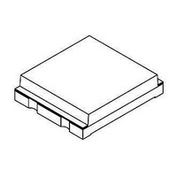
Package / Case
SMD-4
Maximum Operating Temperature
+ 100 C
Minimum Operating Temperature
- 40 C
Wavelength Typ
940nm
Half Angle
65°
Dark Current
2nA
Diode Case Style
SMD
No. Of Pins
2
Operating Temperature Range
-40°C To +100°C
Size
5mm X 4.24mm X 1.12mm
Reverse Voltage Vr
60V
Photodiode Type
PIN
Polarity
Forward
Reverse Breakdown Voltage
60V
Forward Voltage
1.3V
Dark Current (max)
30nA
Power Dissipation
215mW
Light Current
35uA
Rise Time
100ns
Fall Time
100ns
Operating Temp Range
-40C to 100C
Operating Temperature Classification
Industrial
Mounting
Surface Mount
Pin Count
4
Package Type
SMD
Lead Free Status / RoHS Status
Lead free / RoHS Compliant
Lead Free Status / RoHS Status
Lead free / RoHS Compliant, Lead free / RoHS Compliant


TEMD5120X01
Vishay Semiconductors
Note
T
BASIC CHARACTERISTICS
T
www.vishay.com
462
amb
amb
BASIC CHARACTERISTICS
PARAMETER
Forward voltage
Breakdown voltage
Reverse dark current
Diode capacitance
Open circuit voltage
Temperature coefficient of V
Short circuit current
Temperature coefficient of I
Reverse light current
Angle of half sensitivity
Wavelength of peak sensitivity
Range of spectral bandwidth
Noise equivalent power
Rise time
Fall time
= 25 °C, unless otherwise specified
Fig. 1 - Reverse Dark Current vs. Ambient Temperature
= 25 °C, unless otherwise specified
94 8403
1000
100
10
1
20
T
amb
40
- Ambient Temperature (°C)
k
o
60
For technical questions, contact: detectortechsupport@vishay.com
V
R
Silicon PIN Photodiode, RoHS Compliant, Released for
Lead (Pb)-free Reflow Soldering, AEC-Q101 Released
= 10 V
E
E
E
E
E
V
V
80
e
e
e
e
e
R
R
= 1 mW/cm
V
= 1 mW/cm
= 1 mW/cm
= 1 mW/cm
= 1 mW/cm
V
V
= 0 V, f = 1 MHz, E = 0
= 3 V, f = 1 MHz, E = 0
R
TEST CONDITION
R
R
I
R
V
= 10 V, λ = 950 nm
= 10 V, R
= 10 V, R
= 100 µA, E = 0
R
λ = 820 nm
λ = 820 nm
I
= 10 V, E = 0
F
V
100
= 50 mA
R
= 5 V
2
2
2
2
2
, λ = 950 nm,
, λ = 950 nm
, λ = 950 nm
, λ = 950 nm
, λ = 950 nm
L
L
= 1 kΩ,
= 1 kΩ,
Fig. 2 - Relative Reverse Light Current vs. Ambient Temperature
SYMBOL
V
TK
NEP
TK
λ
C
C
V
V
(BR)
I
I
λ
I
ϕ
t
t
ro
ra
0.5
k
r
D
D
p
f
F
o
Vo
Ik
94 8409
1.4
1.2
1.0
0.8
0.6
0
MIN.
60
25
T
20
amb
- Ambient Temperature (°C)
790 to 1050
4 x 10
λ = 950 nm
V
40
TYP.
- 2.6
± 65
350
940
100
100
0.1
R
48
17
32
35
1
2
= 5 V
-14
60
Document Number: 84680
MAX.
1.3
30
40
80
Rev. 1.5, 26-Feb-09
100
W/√Hz
mV/K
UNIT
%/K
deg
mV
nm
nm
nA
µA
µA
pF
pF
ns
ns
V
V
Related parts for TEMD5120X01
Image
Part Number
Description
Manufacturer
Datasheet
Request
R

Part Number:
Description:
357-036-542-201 CARDEDGE 36POS DL .156 BLK LOPRO
Manufacturer:
Vishay
Datasheet:
Part Number:
Description:
357-036-542-201 CARDEDGE 36POS DL .156 BLK LOPRO
Manufacturer:
Vishay
Datasheet:
Part Number:
Description:
357-036-542-201 CARDEDGE 36POS DL .156 BLK LOPRO
Manufacturer:
Vishay
Datasheet:
Part Number:
Description:
357-036-542-201 CARDEDGE 36POS DL .156 BLK LOPRO
Manufacturer:
Vishay
Datasheet:
Part Number:
Description:
357-036-542-201 CARDEDGE 36POS DL .156 BLK LOPRO
Manufacturer:
Vishay
Datasheet:
Part Number:
Description:
357-036-542-201 CARDEDGE 36POS DL .156 BLK LOPRO
Manufacturer:
Vishay
Datasheet:
Part Number:
Description:
357-036-542-201 CARDEDGE 36POS DL .156 BLK LOPRO
Manufacturer:
Vishay
Datasheet:
Part Number:
Description:
357-036-542-201 CARDEDGE 36POS DL .156 BLK LOPRO
Manufacturer:
Vishay
Datasheet:
Part Number:
Description:
357-036-542-201 CARDEDGE 36POS DL .156 BLK LOPRO
Manufacturer:
Vishay
Datasheet:
Part Number:
Description:
357-036-542-201 CARDEDGE 36POS DL .156 BLK LOPRO
Manufacturer:
Vishay
Datasheet:
Part Number:
Description:
357-036-542-201 CARDEDGE 36POS DL .156 BLK LOPRO
Manufacturer:
Vishay
Datasheet:
Part Number:
Description:
357-036-542-201 CARDEDGE 36POS DL .156 BLK LOPRO
Manufacturer:
Vishay
Datasheet:
Part Number:
Description:
357-036-542-201 CARDEDGE 36POS DL .156 BLK LOPRO
Manufacturer:
Vishay
Datasheet:
Part Number:
Description:
357-036-542-201 CARDEDGE 36POS DL .156 BLK LOPRO
Manufacturer:
Vishay
Datasheet:
Part Number:
Description:
357-036-542-201 CARDEDGE 36POS DL .156 BLK LOPRO
Manufacturer:
Vishay
Datasheet: