TSL1406RS TAOS, TSL1406RS Datasheet - Page 9
TSL1406RS
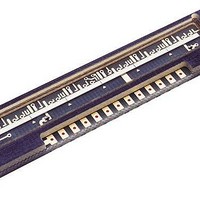
Manufacturer Part Number
TSL1406RS
Description
Photodiodes 400 DPI SENSOR
Manufacturer
TAOS
Type
Linear Sensor Arrayr
Datasheet
1.TSL1406RS.pdf
(14 pages)
Specifications of TSL1406RS
Peak Wavelength
1000 nm
Maximum Rise Time
500 ns
Maximum Fall Time
500 ns
Maximum Operating Temperature
+ 70 C
Minimum Operating Temperature
0 C
Mounting Style
SMD/SMT
Product
Photodiode
Lead Free Status / RoHS Status
Lead free / RoHS Compliant


Integration Time
The LUMENOLOGY r Company
The integration time of the linear array is the period during which light is sampled and charge accumulates on
each pixel’s integrating capacitor. The flexibility to adjust the integration period is a powerful and useful feature
of the TAOS TSL14xx linear array family. By changing the integration time, a desired output voltage can be
obtained on the output pin while avoiding saturation for a wide range of light levels.
The integration time is the time between the SI (Start Integration) positive pulse and the HOLD positive pulse
minus the 18 setup clocks. The TSL14xx linear array is normally configured with the SI and HOLD pins tied
together. This configuration will be assumed unless otherwise noted. Sending a high pulse to SI (observing
timing rules for setup and hold to clock edge) starts a new cycle of pixel output and integration setup. However,
a minimum of (n+1) clocks, where n is the number of pixels, must occur before the next high pulse is applied
to SI. It is not necessary to send SI immediately on/after the (n+1) clocks. A wait time adding up to a maximum
total of 100 ms between SI pulses can be added to increase the integration time creating a higher output voltage
in low light applications.
Each pixel of the linear array consists of a light-sensitive photodiode. The photodiode converts light intensity
to a voltage. The voltage is sampled on the Sampling Capacitor by closing switch S2 (position 1) (see the
Functional Block Diagram on page 1). Logic controls the resetting of the Integrating Capacitor to zero by closing
switch S1 (position 2).
At SI input, all of the pixel voltages are simultaneously scanned and held by moving S2 to position 2 for all pixels.
During this event, S2 for pixel 1 is in position 3. This makes the voltage of pixel 1 available on the analog output.
On the next clock, S2 for pixel 1 is put into position 2 and S2 for pixel 2 is put into position 3 so that the voltage
of pixel 2 is available on the output.
Following the SI pulse and the next 17 clocks after the SI pulse is applied, the S1 switch for all pixels remains
in position 2 to reset (zero out) the integrating capacitor so that it is ready to begin the next integration cycle.
On the rising edge of the 19
a new integration cycle.
The first 18 pixel voltages are output during the time the integrating capacitor is being reset. On the 19
following an SI pulse, pixels 1 through 18 have switch S2 in position 1 so that the sampling capacitor can begin
storing charge. For the period from the 19
voltage during the n
the integrating capacitor voltage. For example, S2 for pixel 19 moves to position 1 on the 20
clock, the S2 switch for the last (n
If a SI was initiated on the n+1 clock, there would be no time for the sampling capacitor of pixel n to charge to
the voltage level of the integrating capacitor. The minimum time needed to guarantee the sampling capacitor
for pixel n will charge to the voltage level of the integrating capacitor is the charge transfer time of 20 μs.
Therefore, after n+1 clocks, an extra 20 μs wait must occur before the next SI pulse to start a new integration
and output cycle.
The minimum integration time for any given array is determined by time required to clock out all the pixels
in the array and the time to discharge the pixels. The time required to discharge the pixels is a constant.
Therefore, the minimum integration period is simply a function of the clock frequency and the number of pixels
in the array. A slower clock speed increases the minimum integration time and reduces the maximum light level
for saturation on the output. The minimum integration time shown in this data sheet is based on the maximum
clock frequency of 8 MHz.
th
clock. On the next clock the previous pixel S2 switch is put into position 1 to start sampling
th
clock, the S1 switch for all the pixels is put into position 1 and all of the pixels begin
th
APPLICATION INFORMATION
) pixel is put into position 1 and the output goes to a high-impedance state.
r
th
www.taosinc.com
clock through the n
768 × 1 LINEAR SENSOR ARRAY WITH HOLD
th
clock, S2 is put into position 3 to read the output
r
TSL1406R, TSL1406RS
Copyright E 2007, TAOS Inc.
th
TAOS042D − APRIL 2007
clock. On the n+1
th
clock
9
Related parts for TSL1406RS
Image
Part Number
Description
Manufacturer
Datasheet
Request
R

Part Number:
Description:
Microcontroller Modules & Accessories TAOS Eval Module w/USB Interface
Manufacturer:
TAOS
Part Number:
Description:
Optical Sensor Development Tools TAOS Eval Module
Manufacturer:
TAOS

Part Number:
Description:
Industrial Optical Sensors Ambient Light Sensor SMBus
Manufacturer:
TAOS
Datasheet:

Part Number:
Description:
Photodiodes TriColor Sensor RGB, Clear Ch
Manufacturer:
TAOS
Datasheet:

Part Number:
Description:
LED Displays Hexadecimal Display 4-bit
Manufacturer:
TAOS
Datasheet:

Part Number:
Description:
Photodiodes Linear Sensor Array 200dpi 64pix
Manufacturer:
TAOS
Datasheet:

Part Number:
Description:
Industrial Optical Sensors Ambient Light Sensor SMBus
Manufacturer:
TAOS
Datasheet:

Part Number:
Description:
Photodiodes Linear Array 200 DPI
Manufacturer:
TAOS
Datasheet:

Part Number:
Description:
Photodiodes Light to Voltage Converter
Manufacturer:
TAOS
Datasheet:

Part Number:
Description:
Photodiodes Linear Array 200 DPI
Manufacturer:
TAOS
Datasheet:
Part Number:
Description:
Industrial Optical Sensors Ambient Light Sensor SMBus
Manufacturer:
TAOS
Datasheet:
Part Number:
Description:
Photodiodes TriColor Sensor RGB, Clear Ch
Manufacturer:
TAOS
Datasheet:
Part Number:
Description:
LED Displays Hexadecimal Display 4-bit
Manufacturer:
TAOS
Datasheet:
Part Number:
Description:
Photodiodes Linear Sensor Array 200dpi 64pix
Manufacturer:
TAOS
Datasheet:
