E3T-SL11 Omron, E3T-SL11 Datasheet - Page 13
E3T-SL11
Manufacturer Part Number
E3T-SL11
Description
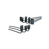
Industrial Photoelectric Sensors NPN CONVERGENT-BEAM
Manufacturer
Omron
Type
Subminiature Photoelectric Sensorr
Series
E3Tr
Specifications of E3T-SL11
Features
Offered in both flat and rectangular
Sensing Method
Limited Reflective
Sensing Distance
5 mm to 15 mm
Light Source
Red LED
Connection
Pre-leaded
Output Configuration
NPN
Output Current
50mA
Sensor Output
NPN LO
Supply Voltage Range Dc
12V To 24V
Length/height, External
20.6mm
Sensor Housing
Rectangular
Sensor Input
Optical
Output Type
Transistor
External Width
7mm
Switch Terminals
Cable
Rohs Compliant
Yes
Sensing Object
White Paper
Sensing Light
Red
Mounting Type
Bracket Mount
Current - Supply
20mA
Voltage - Supply
12 V ~ 24 V
Package / Case
Module, Pre-Wired
External Depth
11.2mm
Sensing Mode
Convergent
Lead Free Status / RoHS Status
Lead free / RoHS Compliant
Lead Free Status / RoHS Status
Lead free / RoHS Compliant, Lead free / RoHS Compliant
Available stocks
Company
Part Number
Manufacturer
Quantity
Price
Company:

Part Number:
E3T-SL11
Manufacturer:
OMRON
Quantity:
492


I/O Circuit Diagrams
NPN Output
PNP Output
* Models numbers for Through-beam Sensors (E3T-@T@@) are for sets that include both the Emitter and Receiver.
Plugs (Sensor I/O Connectors)
M12 Connector
e-CON connector
E3T-@@@1
E3T-@@@2
E3T-@@@3
E3T-@@@4
The model number of the Emitter is expressed by adding "-L" to the set model number (example: E3T-ST11-L 2M), the model number of the Receiver, by adding "-D" (example:
E3T-ST11-D 2M.) Refer to Ordering Information to confirm model numbers for Emitter and Receivers.
1
15.8
Model
Model
2
4
3
E39-ECON@M
E39-ECONW@M
*
*
1
2
3
4
Operation mode
Operation mode
Light-ON
Dark-ON
Light-ON
Dark-ON
XS5F-D421-D80-A
XS5F-D421-G80-A
Operation indicator
(orange)
Output
transistor
Load
(e.g., relay)
Operation indicator
(orange)
Output
transistor
Load
(e.g., relay)
Operation indicator
(orange)
Output
transistor
Load
(e.g., relay)
Operation indicator
(orange)
Output
transistor
Load
(e.g., relay)
Light interrupted
Light interrupted
Light interrupted
Light interrupted
Light incident
Light incident
Light incident
Wire color
Light incident
Timing charts
Timing charts
Brown
White
Blue
Black
Operate
Operate
Operate
Operate
Reset
Reset
Reset
Reset
OFF
OFF
OFF
OFF
OFF
OFF
OFF
OFF
ON
ON
ON
ON
ON
ON
ON
ON
Pin arrangement
(Between brown (1)
and black (4) leads)
(Between brown (1)
and black (4) leads)
Note: Pin 2 is not used.
(Between blue (3)
and black (4) leads)
(Between blue (3)
and black (4) leads)
Classification
DC
Wire color Connector pin No.
Through-beam Receivers,
Retroreflective and Reflective Models
Through-beam Emitters
Through-beam Receivers,
Retroreflective and Reflective Models
Through-beam Emitters
Brown
Operation
indicator
(orange)
Operation
indicator
(orange)
White
Black
Blue
Photo-
electric
Sensor
Main
Circuit
Photo-
electric
Sensor
Main
Circuit
Stability
indicator
(green)
Stability
indicator
(green)
Photo-
electric
Sensor
Main
Circuit
Photo-
electric
Sensor
Main
Circuit
1
2
3
4
3
1
1
3
Brown
Brown
Blue
Blue
Output circuit
Output circuit
(Control output)
(Control output)
12 to 24 VDC
12 to 24 VDC
ZD
ZD
Note:Pin 2 is not used.
Power supply (0 V)
Note:Pin 2 is not used.
Power supply (+V)
1
4
3
1
4
3
Brown
Black
Blue
Black
Application
Brown
Blue
Connector Pin Arrangement
Connector Pin Arrangement
Pins 2 and 4 are not used
with
Pins 2 and 4 are not used
with
Output
50 mA
max.
50 mA
max.
---
Through-beam Emitters.
Through-beam Emitters.
2
M12
2
M12
1
3
1
3
12 to 24 VDC
4
4
12 to 24 VDC
(relay)
(relay)
Load
Load
0 V
0 V
1
2
3
4
1
2
3
4
e-CON
e-CON
E3T
13
Related parts for E3T-SL11
Image
Part Number
Description
Manufacturer
Datasheet
Request
R

Part Number:
Description:
PHOTO MINI S/V THRU PNP LO
Manufacturer:
Omron
Datasheet:
Part Number:
Description:
PHOTO MINI S/V THRU PNP DO
Manufacturer:
Omron
Datasheet:
Part Number:
Description:
Industrial Photoelectric Sensors Photo Mini S/V Conve PNP LO
Manufacturer:
Omron
Datasheet:
Part Number:
Description:
PHOTO MINI S/V CONVER PNP LO
Manufacturer:
Omron
Datasheet:
Part Number:
Description:
Photoelectric Sensors - Industrial PHOTO MINI S/V CONVER PNP DO
Manufacturer:
Omron
Datasheet:
Part Number:
Description:
PHOTO MINI S/V CONVER PNP DO
Manufacturer:
Omron
Datasheet:

Part Number:
Description:
PHOTO MINI S/V CONVER PNP LO
Manufacturer:
Omron
Datasheet:
Part Number:
Description:
PHOTO MINI S/V CONVER PNP DO
Manufacturer:
Omron
Datasheet:
Part Number:
Description:
PHOTO MINI S/V CONVER PNP LO
Manufacturer:
Omron
Datasheet:
Part Number:
Description:
PHOTO MINI S/V CONVER PNP DO
Manufacturer:
Omron
Datasheet:

Part Number:
Description:
G6S-2GLow Signal Relay
Manufacturer:
Omron Corporation
Datasheet:
Part Number:
Description:
Compact, Low-cost, SSR Switching 5 to 20 A
Manufacturer:
Omron Corporation
Datasheet:
Part Number:
Description:
Manufacturer:
Omron Corporation
Datasheet: