S20DC100 TELEDYNE, S20DC100 Datasheet

Solid State Relays 100A. 200 VDC DC Switch

S20DC100

Manufacturer Part Number
S20DC100
Description
Solid State Relays 100A. 200 VDC DC Switch
Manufacturer
TELEDYNE
Datasheet

Specifications of S20DC100

Control Voltage Range
4.5 VDC to 32 VDC
Load Voltage Rating
200 V
Load Current Rating
100 A
Output Device
MOSFET
Mounting Style
SMD/SMT
Relay Type
DC Solid State
Turn-on Switching
DC
Termination Style
Screw
Application
To avoid linear control risks
Brand/series
S Series
Current, Leakage, Off-state
250 uAdc
Current, Rating
100 A
Dimensions
2.29 in. L x 1.75 in. W x 1.10 in. H
Function
General Purpose
Resistance, Thermal, Junction To Case
8 °C⁄W
Standards
CE
Temperature, Ambient, Maximum
100 °C
Temperature, Ambient, Minimum
-40 °C
Termination
Screw
Voltage, Control
32 VDC
Voltage, Rating
200 VDC
Lead Free Status / RoHS Status
Lead free / RoHS Compliant
© 2006 TELEDYNE RELAYS
FEATURES/BENEFITS
• Latest generation MOSFET technology
• Ultra low on-state resistance
• Innovative isolated driver ensures fast power transistor turn on and off and thus low
• Ultra low output leakage current
• Low control current consumption
• Triggered control input to avoid linear control risks
• Low conducted and radiated disturbances
Part Number
S20DC100
Part Number Explanation
Series
NOTES
1) Line Voltage (peak): 20 = 200 Vdc
2) Switch Type: DC = DC
Control Range
Input Current Range
Typical Turn-On Voltage
Must Turn-Off Voltage
Reverse Voltage
Reverse Leakage Current
(+25°C ambient temperature unless otherwise specified)
power transient
S
45
40
35
30
25
20
15
10
5
0
0
2
INPUT (CONTROL) SPECIFICATIONS
Line Voltage
4
ELECTRICAL SPECIFICATIONS
CONTROL CHARACTERISTIC
6
20
8
Description
100A, 200 Vdc Solid-State Relay
10 12 14 16 18 20 22 24 26 28 30 32
1
Control Voltage (V)
Figure 2
Switch Type
DC
Min
Output Current – Amps
4.5
4.3
25
1
2
(800) 284-7007 • www.teledynerelays.com
Max
100
32
42
32
100
@25°C
Units
mAdc
Vdc
Vdc
Vdc
Vdc
µA
+ 3
– 4
1.01 (25.8)
1.10 (28)
0.89 (22.8)
Tolerances: Ø0.3
Dimensions in inches (mm)
weight: 3.52 oz. (100g)
(19.6)
0.77
IScst
MECHANICAL SPECIFICATION
Ø0.5
LED
NEW Series S20DC100
Single pulse
ON & OFF
BLOCK DIAGRAM
circuit
turn
Ø4.7
Figure 1
Figure 3
PhV
1+
4–
Output to 100A, 200 Vdc
1.75 (44.5)
1.10 (28)
1.0 (25.4)
DC Solid-State Relay
Driver
(OFF)
2–
3+
MOSFET
S20DC100 Page 1
S20DC100\062006\Q1
M5
M3
1 +
2 +

Related parts for S20DC100

S20DC100 Summary of contents

Page 1

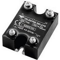
... NEW Series S20DC100 Output to 100A, 200 Vdc DC Solid-State Relay 1.10 (28) Ø4.7 M5 2– 1+ 4– 3+ 1.0 (25.4) 1.75 (44.5) M3 Figure 1 BLOCK DIAGRAM MOSFET PhV Driver (OFF) Single pulse turn ON & OFF circuit Figure 3 S20DC100 Page 1 S20DC100\062006\ ...

Page 2

... TIME DIAGRAMS TURN-ON Vc (control) Vt (switch) tdon TURN-OFF Vc (control) Vt (switch) tdoff Figure 6 S20DC100 Page 2 SPECIFICATIONS ARE SUbjECT TO ChANgE wIThOUT NOTICE NEW Series S20DC100 HIGH SIDE WIRING DIAGRAM (Load Connected to “—”) DC Control Power Supply + – Max Units 130 Vdc 200 Vpeak ...

Page 3

... Tabs, Eyelet Type) M5 MISCELLANEOUS Display green LED (ON) housing Mounting 2 screws (M4x12mm) Noise Level No audible noise © 2006 TELEDYNE RELAYS NEW Series S20DC100 Please refer to the installation notice for 0.3°C/W 0.3°C/W 0.1°C/W 2.1°C/W 1.95°C/W 1.5°C/W 1.3°C ...

Related keywords