UM232R FTDI, UM232R Datasheet
UM232R
Specifications of UM232R


Related parts for UM232R


UM232R Summary of contents
Page 1
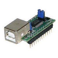
... USB, thus forming the basis of a security dongle which can be used to protect customer application software from being copied. The UM232R is supplied on a PCB which is designed to plug into a standard 15.0mm (0.6” ) wide 24 pin DIP socket. All components used, including the FT232RL are Pb-free (RoHS compliant). ...
Page 2
... PDA to USB data transfer • USB Smart Card Readers • USB Instrumentation UM232R USB-Serial UART Development Module Datasheet Version 1.02 • Support for USB suspend and resume. • Support for bus powered, self powered, and high- power bus powered USB configurations. ...
Page 3
... This section summarises the key features and enhancements of the FT232RL IC device which is used on the UM232R Module. For further details, consult the FT232R datasheet, which is available from the Integrated Clock Circuit - Previous generations of FTDI’s USB UART devices required an external crystal or ceramic resonator ...
Page 4
... FTDI driver will calculate the required divisor, and set the baud rate. See FTDI application note AN232B-05 for more details. UM232R USB-Serial UART Development Module Datasheet Version 1.02 FTDI website ...
Page 5
... QFN-32 package ( FT232RQ). Both packages are lead ( Pb ) free, and use a ‘green’ compound. Both packages are fully compliant with European Union directive 2002/95/EC. Figure 1 - The UM232R Module. UM232R USB-Serial UART Development Module Datasheet Version 1.02 © Future Technology Devices International Ltd. 2005 ...
Page 6
... UM232R © FTDI 2005 1 TXD 1 J1 DTR# RTS# VIO RXD RI# GND DSR# DCD# CTS# J2 CB4 CB2 12 Figure 2 - Module Pin Out and Jumper locations. UM232R USB-Serial UART Development Module Datasheet Version 1. GND 24 CB0 CB1 VCC RST 3V3 CB3 PU1 PU2 2 1 VCC USB SLD 13 ...
Page 7
... J2 pins 1 and 2 together (this is the module default configuration). In this case these pins Output would have the same description as pin 14. To use the UM232R module in a self powered configuration ensure that jumper J2 pins 1 and 2 are not con- nected together, and apply an external 3.3V to 5.25V supply to one of these pins. 16 ...
Page 8
... CBUS0, CBUS1, CBUS2, CBUS3 BitBangWRn CBUS0, CBUS1, CBUS2, CBUS3 BitBangRDn CBUS0, CBUS1, CBUS2, CBUS3 UM232R USB-Serial UART Development Module Datasheet Version 1.02 FTDI website. The default Description Enable transmit data for RS485 Goes low after the device is configured by USB, then high during USB suspend ...
Page 9
... The date code format is YYXX where digit week number digit year number. The UM232R module uses exclusivly lead free components. Both the I.C. device and the module are fully compliant with European Union directive 2002/95/EC. UM232R USB-Serial UART Development Module Datasheet Version 1.02 7.50mm 5.50mm (0.30" ...
Page 10
... Voh Output Voltage High Vol Output Voltage Low Vin Input Switching Threshold VHys Input Switching Hysteresis UM232R USB-Serial UART Development Module Datasheet Version 1.02 Value -65°C to 150°C 168 Hours (IPC/JEDEC J-STD-033A MSL Level 3 Compliant)* -40°C to 85°C -0.5 to +6.00 -0.5 to +3.8 -0 ...
Page 11
... Single Ended Rx Threshold UCom Differential Common Mode UVDif Differential Input Sensitivity UDrvZ Driver Output Impedance ***Driver Output Impedance includes the internal USB series resistors on USBDP and USBDM pins. UM232R USB-Serial UART Development Module Datasheet Version 1.02 Min Typ Max Units 2.1 2.6 3 ...
Page 12
... Read / Write Cycles 5.4 Internal Clock Characteristics The internal Clock Oscillator has the following characteristics. Table 16 - Internal Clock Characteristics Parameter Frequency of Operation Clock Period Duty Cycle UM232R USB-Serial UART Development Module Datasheet Version 1.02 Value Unit 15 Years 100,000 Cycles Value Unit ...
Page 13
... No device can draw more that 500mA from the USB Bus. Interfacing the UM232R module to a microcontroller (MCU), or other logic for a bus powered design would be done in exactly the same way as for a self powered design (see Section 6.2), except that the MCU or external logic would take its power supply from the USB bus (either the 5V on the USB pin ...
Page 14
... MCU Figure 5 - Self Powered Configuration Figure 5 illustrates the UM232R in a typical USB self powered configuration. In this case the link on jumper J2 is removed, and an external supply is connected to the module VCC pins. Figure 5 illustrates a self powered design which has a 3. supply. ...
Page 15
... PWREN# signal gets its VCC supply from VCCIO). Either connect the power switch between the output of the 3.3V regulator and the external 3.3V logic or power VCCIO from the 3V3OUT pin of the FT232R. UM232R USB-Serial UART Development Module Datasheet Version 1.02 TXD 1 ...
Page 16
... The FT232R’s VCCIO pin is either supplied with 5V from the USB bus (connect together pins 2 and 3 on J1), or with 3.3V from the FT232R’s 3V3OUT pin (connect together pins 1 and shown). The supply to UM232R’s 3V3 pin can also be used to supply up to 50mA to external logic. Please note the following in relation to bus powered designs of this type - ...
Page 17
... UM232R Module Circuit Schematic Figure 8 - Module Circuit Schematic UM232R USB-Serial UART Development Module Datasheet Version 1.02 © Future Technology Devices International Ltd. 2005 ...
Page 18
... Version 2.8a or later is required for the FT232R chip. Users who do not have their own USB Vendor ID but who would like to use a unique Product ID in their design can apply to FTDI for a free block of unique PIDs. Contact FTDI support UM232R USB-Serial UART Development Module Datasheet Version 1.02 Value 0403h 6001h ...
Page 19
... Fax: +886 2 8791 3576 tw.sales@ftdichip.com E-Mail (Sales): E-Mail (Support): tw.support@ftdichip.com E-Mail (General Enquiries): tw.admin@ftdichip.com Website URL : http://www.ftdichip.com UM232R USB-Serial UART Development Module Datasheet Version 1.02 Future Technology Devices International Ltd. (USA) 5285 NE Elam Young Parkway, Suite B800 Hillsboro, OR 97124-6499 USA Tel.: +1 (503) 547-0988 ...