USB-RS232-PCBA FTDI, USB-RS232-PCBA Datasheet - Page 10
USB-RS232-PCBA
Manufacturer Part Number
USB-RS232-PCBA
Description
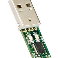
Interface Modules & Development Tools USB to RS232 Embeded Converter PCB Assy
Manufacturer
FTDI
Datasheet
1.USB-RS232-PCBA.pdf
(16 pages)
Specifications of USB-RS232-PCBA
Interface Type
USB, RS-232
Data Bus Width
Serial
Operating Supply Voltage
5 V
Product
Interface Modules
For Use With/related Products
FT232R
Lead Free Status / RoHS Status
Lead free / RoHS Compliant


4.1
Table 4.1 USB-RS232-PCB Signal Descriptions
4.2
Selection of whether the POWER signal is GND, +3.3V or +5V is done using resistors. The following table
gives details of what resistors are required for the different voltage levels.
Resistor
Table 4.2 UART Signal Level Selection
Fitted
Fitted
Fitted
POWER
Name
CTS#
RTS#
Not
Not
R2
GND
TXD
RXD
USB-RS232-PCB Signal Descriptions
USB-RS232-PCB +5V/+3.3V Selection
Resistor
Fitted
Fitted
Fitted
Not
Not
R3
Output
Output
Output
Input
Input
Type
GND
Copyright © 2011 Future Technology Devices International Limited
Description
VCC floats
POWER Signal is +3.3V
POWER Signal is +5.0V
Description
Device ground supply pin.
Clear to Send Control input / Handshake signal.
Power output. Default is GND, but can be customised to
output +3.3V or +5V. If required, contact FTDI Sales Team
(sales1@ftdichip.com)
Transmit Asynchronous Data output.
Receive Asynchronous Data input.
Request To Send Control Output / Handshake signal.
USB TO RS232 UART SERIAL CONVERTER
Document Reference No.: FT_000079
PCB
Clearance No.: FTDI# 52
Datasheet Version 1.41
9
Related parts for USB-RS232-PCBA
Image
Part Number
Description
Manufacturer
Datasheet
Request
R

Part Number:
Description:
MODULE USB - RS232 WITH CABLE
Manufacturer:
FTDI, Future Technology Devices International Ltd
Datasheet:
Part Number:
Description:
CABLE USB RS232 3.3V WIRE 1.8M
Manufacturer:
FTDI, Future Technology Devices International Ltd
Datasheet:

Part Number:
Description:
CABLE USB RS232 3.3V WIRE END 5M
Manufacturer:
FTDI, Future Technology Devices International Ltd
Datasheet:

Part Number:
Description:
CABLE USB RS232 WIRE END 5M
Manufacturer:
FTDI, Future Technology Devices International Ltd
Datasheet:

Part Number:
Description:
CABLE USB RS232 5V WIRE END 5M
Manufacturer:
FTDI, Future Technology Devices International Ltd
Datasheet:

Part Number:
Description:
Interface Modules & Development Tools USB HS to RS232 Conv Assembly 2 DB9 Ports
Manufacturer:
FTDI
Datasheet:

Part Number:
Description:
Interface Modules & Development Tools USB to RS232 Convrtr Assembly 1 DB9 Port
Manufacturer:
FTDI
Datasheet:

Part Number:
Description:
Interface Modules & Development Tools USB HS to RS232 Conv Assembly 4 DB9 Ports
Manufacturer:
FTDI
Datasheet:

Part Number:
Description:
MODULE USB TO RS232 CONV SGL
Manufacturer:
FTDI, Future Technology Devices International Ltd
Datasheet:

Part Number:
Description:
MODULE USB TO RS232 CONV DUAL HS
Manufacturer:
FTDI, Future Technology Devices International Ltd
Datasheet:

Part Number:
Description:
USB
Manufacturer:
Samtec Inc
Datasheet:

Part Number:
Description:
IC USB TO SERIAL UART 32-QFN
Manufacturer:
FTDI, Future Technology Devices International Ltd

Part Number:
Description:
USB Interface IC USB to Serial UART Enhanced IC SSOP-28
Manufacturer:
FTDI
Datasheet:

Part Number:
Description:
IC, USB UART INTERFACE, SSOP-28
Manufacturer:
FTDI
Datasheet:

Part Number:
Description:
IC, USB UART INTERFACE, QFN-32
Manufacturer:
FTDI
Datasheet: