MPM-DC-KIT Actel, MPM-DC-KIT Datasheet
MPM-DC-KIT
Specifications of MPM-DC-KIT


Related parts for MPM-DC-KIT


MPM-DC-KIT Summary of contents
Page 1
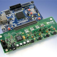
... Mixed Signal Power Manager Daughter Card Kit Quickstart Card Kit Contents – MPM-DC-KIT (RoHS compliant) Quantity 1 Mixed Signal Power Manager Daughter Card Kit power supply Rubber Feet. If using the MPM-DC with the SmartFusion Evaluation Kit, remove the 4 legs and replace with rubber feet to match the board height. ...
Page 2
... Mixed Signal Power Manager Daughter Card Kit Quickstart Card Connections, Jumper Switches, and Settings Connect jumpers in the default settings to enable the MPM for SmartFusion design to function correctly before powering up the boards. • Jumpers from FB (feedback voltage) of each regulator for voltage trimming – ...
Page 3
... PC for programming. Also connect the other USB cable to the USB connection on the board and to your PC. From the MPM GUI, select File > Write Device to load the MPM design to the device for the first time. Use the switches on the evaluation or development kit to activate the power-up sequence. You can then create interrupts and change POT settings to review the performance of the board ...
Page 4
... Mixed Signal Power Manager Daughter Card Kit Quickstart Card Documentation Resources For full information on the daughter card and the usage of the MPM GUI, refer to the MPM User's Guide, Mixed Signal Power Manager Kit website page: http://www.actel.com/products/hardware/devkits_boards/mpm_dc.aspx#rsc The source files for the reference design are also available to allow you to adapt and develop your own power management designs ...