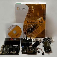
Z16FMC28200KITG Zilog, Z16FMC28200KITG Datasheet - Page 5

Z16FMC28200KITG
Manufacturer Part Number
Z16FMC28200KITG
Description
Power Management Modules & Development Tools Z16Motor Control Development Kit
Manufacturer
Zilog
Type
Motor / Motion Controllers & Driversr
Datasheet
1.Z16FMC28200KITG.pdf
(15 pages)
Specifications of Z16FMC28200KITG
Interface Type
RS-232
Operating Supply Voltage
5 V
Product
Power Management Development Tools
For Use With/related Products
Z16FMC
Lead Free Status / RoHS Status
Lead free / RoHS Compliant
Lead Free Status / RoHS Status
Lead free / RoHS Compliant
Step 3. Configure the 5 V DC Universal Power Supply
The universal power supply kit features different plug adapters in one box and the power
supply in another. The power supply ships with a slide-out plate that must be removed to
insert the location-specific plug adapter.
Observe the following steps to configure the 5 V DC universal power supply:
1. Remove the slide-out plate.
2. Select the AC plug adapter appropriate for your locale and insert it into the slot that re-
3. Slide the new plug adapter into the slot until it snaps into place.
For convenience, you can leave the adapter slot cover in place and plug in a standard com-
puter equipment AC power cord (purchased separately) between the AC cord receptacle
on the end of the power supply and an electrical outlet.
Step 4. Connect the 5 V DC Universal Power Supply
Connect the 5 V DC power supply to the MC MDS board at connector P2, then plug the
supply into an electrical outlet. The green 3.3 V DC LED D1 illuminates when power is
applied.
Step 5. Connect the Adjustable Power Supply
1. Set your adjustable power supply to 0 V DC.
2. Connect the negative (
3. Connect the positive (+) lead of your adjustable power supply to spade lug connector
Step 6. Apply Power to the Motor
1. Slowly increase the adjustable power supply to 24 V DC. The 3-phase motor begins to
QS007901-1110
mains after removing the slide-out plate.
P5 on the 3-Phase Motor Control Application Board.
P4 on the 3-Phase Motor Control Application Board.
spin.
Caution:
To avoid damage to the development kit, check the power supply con-
nection polarities as you follow the instructions below.
–
) lead of your adjustable power supply to spade lug connector
Z16FMC Series Motor Control Development Kit
Quick Start Guide
Page 5 of 15


