AVR-CAN Olimex Ltd., AVR-CAN Datasheet
AVR-CAN
Specifications of AVR-CAN
Available stocks


Related parts for AVR-CAN


AVR-CAN Summary of contents
Page 1
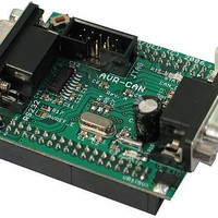
... AVR-CAN development board Copyright(c) 2011, OLIMEX Ltd, All rights reserved Users Manual Rev.A, January 2010 Page 1 ...
Page 2
... FR-4, 1.5 mm (0.062''), soldermask, white silkscreen component print Dimension 60x50 mm (2.36x1.96'') ELECTROSTATIC WARNING: The AVR-CAN board is shipped in protective anti-static packaging. The board must not be subject to high electrostatic potentials. General practice for working with static sensitive devices should be applied when working with this board. ...
Page 3
... PROCESSOR FEATURES: AVR-CAN board use MCU AT90CAN128 from Atmel with these features: High-performance, Low-power AVR® 8-bit Microcontroller Advanced RISC Architecture Non volatile Program and Data Memories JTAG (IEEE std. 1149.1 Compliant) Interface CAN Controller 2.0A & 2.0B - ISO 16845 Certified ...
Page 4
Output Compare Modulation o 8-channel, 10-bit SAR ADC - 8 Single-ended Channels o 7 Differential Channels o 2 Differential Channels With Programmable Gain at 1x, 10x 200x On-chip Analog Comparator - Byte-oriented Two-wire Serial Interface - Dual Programmable ...
Page 5
BLOCK DIAGRAM: MEMORY MAP: Page 5 ...
Page 6
Page 6 ...
Page 7
SCHEMATIC: 100nF 47uF/6.3VDC + 220uF/25V C17 R13 + Page ...
Page 8
... EXT1-3 and EXT1 you supply VDC to CON2PV2-2.5MM pin 2 (VIN) and GND to CON2PV2-2.5MM pin 1 . The consumption of AVR-CAN is about 40-50 mA. RESET CIRCUIT: AVR-CAN reset circuit is made with R6 (10k) pull-up and button RST. On the board there is a place for the voltage supervisory device MCP120-T, but we sell it without MCP120-T. Page 8 ...
Page 9
... CAN, the jumpers of both devices should be closed. If you have more than two devices, only the two end-devices should be closed. Default state is closed. This jumper when closed supplies VDDA reference to the AVREF. If this jumper is open the desired reference voltage should be applied at EXT2-3. ...
Page 10
EXTERNAL CONNECTORS DESCRIPTION: JTAG: Pin # 1 TCK 2 GND 3 TDO 4 +5V 5 TMS 6 RESET 7 + TDI 10 GND Input Test Data In. This is the serial data input for the shift register. ...
Page 11
Pin # TXD0 3 RXD0 4 NC (not connected through R14 to pin 6) 5 GND 6 NC (not connected through R14 to pin (not connected through R13 to pin (not ...
Page 12
CAN: Pin # CANL 3 GND GND 7 CANH VIN CANL and CANH are either deferential input, or differential output depending on the function of the MCP2551 CAN controller ...
Page 13
EXT1: Pin # 1 VIN 3 GND 5 + T3/INT6/PE6 11 OC3B/INT4/PE4 13 XCK0/AIN0/PE2 15 RXD0/PDI/PE0 17 ADC1/PF1 19 ADC3/PF3 21 ADC5/TMS/PF5 23 ADC7/TDI/PF7 25 PA1/AD1 27 PA3/AD3 29 PA5/AD5 31 PA7/AD7 33 PG1/#RD EXT2: Signal Name ...
Page 14
... Pin # Signal Name 1 VDDA 3 AVREF 5 AGND 7 GND 9 TXD1_OUT 11 PC7/A15/CLK0 13 PC5/A13 15 PC3/A11 17 PC1/A9 19 T0/PD7 21 TXCAN/XCK1/P5 23 TXD1/INT3/PD3 25 SDA/INT1/PD1 27 PB7/OC0A/OC1C 29 PB5/OC1A 31 PB3/MISO 33 PB1/SCK Pin # Signal Name 2 VDDA 4 AGND 6 +5V 8 GND 10 RXD1_IN 12 PC6/A14 14 PC4/A12 16 PC2/A10 18 PC0/A8 20 RXCAN/T1/PD6 22 ICP1/PD4 24 RXD1/INT2/PD2 26 SCL/INT0/PD0 28 PB6/OC1B 30 PB4/OC2A 32 PB2/MOSI 34 PB0/#SS Page 14 ...
Page 15
MECHANICAL DIMENSIONS: Page 15 ...
Page 16
... AVR-CAN Button read demo code (C source and HEX) AVR-CAN RS232 demo code (C source and HEX) ORDER CODE: AVR-CAN – assembled and tested (no kit, no soldering required) How to order? You can order to us directly or by any of our distributors. Check our web All boards produced by Olimex are RoHS compliant Revision history: Board - REV ...
Page 17
... However all warranties implied or expressed including but not limited to implied warranties of merchantability or fitness for purpose are excluded. This document is intended only to assist the reader in the use of the product. OLIMEX Ltd. shall not be liable for any loss or damage arising from the use of any information in this document or any error or omission in such information or any incorrect use of the product ...