LPC-E2468 Olimex Ltd., LPC-E2468 Datasheet - Page 4
LPC-E2468
Manufacturer Part Number
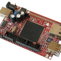
LPC-E2468
Description
MCU, MPU & DSP Development Tools DEV BRD FOR LPC2468 128MBFLASH 16MBSDRAM
Manufacturer
Olimex Ltd.
Datasheet
1.LPC-E2468.pdf
(19 pages)
Specifications of LPC-E2468
Processor To Be Evaluated
LPC2468
Interface Type
Ethernet, USB, I2C, JTAG, SPI, UART
Dimensions
90 mm x 60 mm
Operating Supply Voltage
3.3 V
Silicon Manufacturer
NXP
Core Architecture
ARM
Core Sub-architecture
ARM7TDMI
Silicon Core Number
LPC2xxx
Silicon Family Name
LPC24xx
Kit Contents
Board
Rohs Compliant
Yes
Lead Free Status / RoHS Status
Lead free / RoHS Compliant
Other names
1776321 52R3625


●
●
●
●
●
●
●
●
●
●
Other peripherals:
Standard ARM test/debug interface for compatibility with existing
tools.
Emulation trace module supports real-time trace.
Single 3.3 V power supply (3.0 V to 3.6 V).
Three reduced power modes: idle, sleep, and power-down.
Four external interrupt inputs configurable as edge/level sensitive.
All pins on PORT0 and PORT2 can be used as edge sensitive
interrupt sources.
Processor wake-up from Power-down mode via any interrupt able to
operate during Power-down mode (includes external interrupts, RTC
interrupt, USB activity, Ethernet wake-up interrupt, CAN bus
activity, PORT0/2 pin interrupt).
Two independent power domains allow fine tuning of power
consumption based on needed features.
Each peripheral has its own clock divider for further power saving.
These dividers help reducing active power by 20 - 30 %.
Brownout detect with separate thresholds for interrupt and forced
reset.
▬
▬
▬
▬
▬
▬
▬
▬
▬
▬
▬
▬
▬
▬
▬
Four UARTs with fractional baud rate generation, one with
modem control I/O, one with IrDA support, all with FIFO.
CAN controller with two channels.
SPI controller.
Two SSP controllers, with FIFO and multi-protocol capabilities.
One is an alternate for the SPI port, sharing its interrupt. SSPs
can be used with the GPDMA controller.
Three I
standard port pins).
I
It can be used with the GPDMA.
SD/MMC memory card interface.
160 General purpose I/O pins with configurable pull-up/down
resistors.
10-bit ADC with input multiplexing among 8 pins.
10-bit DAC.
Four general purpose timers/counters with 8 capture inputs
and 10 compare outputs. Each timer block has an external
count input.
Two PWM/timer blocks with support for three-phase motor
control. Each PWM has an external count inputs.
RTC with separate power domain, clock source can be the RTC
oscillator or the APB clock.
2 kB SRAM powered from the RTC power pin, allowing data to
be stored when the rest of the chip is powered off.
WatchDog Timer (WDT). The WDT can be clocked from the
internal RC oscillator, the RTC oscillator, or the APB clock.
2
S (Inter-IC Sound) interface for digital audio input or output.
2
C-bus interfaces (one with open-drain and two with
Related parts for LPC-E2468
Image
Part Number
Description
Manufacturer
Datasheet
Request
R

Part Number:
Description:
MCU, MPU & DSP Development Tools DEV BRD FOR LPC2378 512KB FLASH 16KB RAM
Manufacturer:
Olimex Ltd.

Part Number:
Description:
MCU, MPU & DSP Development Tools HDR BRD FOR LPC2294 1MB SRAM 4MB FLASH
Manufacturer:
Olimex Ltd.

Part Number:
Description:
MCU, MPU & DSP Development Tools DEV BRD FOR LPC2919 768KB FLASH 56KBSRAM
Manufacturer:
Olimex Ltd.
Datasheet:

Part Number:
Description:
MCU, MPU & DSP Development Tools DEV BRD FOR LPC2294 256KB FLASH 16KB RAM
Manufacturer:
Olimex Ltd.
Datasheet:
Part Number:
Description:
MCU, MPU & DSP Development Tools DEV BRD FOR LPC2294 256KB FLASH 16KB RAM
Manufacturer:
Olimex Ltd.
Datasheet:

Part Number:
Description:
MCU, MPU & DSP Development Tools PROTOTYPE BOARD FOR LPC2129
Manufacturer:
Olimex Ltd.

Part Number:
Description:
MCU, MPU & DSP Development Tools PROTOTYPE BRD FOR LPC2138 6V 2-CH
Manufacturer:
Olimex Ltd.

Part Number:
Description:
MCU, MPU & DSP Development Tools DEV BRD FOR LPC2294 256KB FLASH 16KB RAM
Manufacturer:
Olimex Ltd.
Datasheet:

Part Number:
Description:
MCU, MPU & DSP Development Tools PROTOTYPE BRD FOR LPC2148 6V 2-CH
Manufacturer:
Olimex Ltd.
Datasheet:
Part Number:
Description:
MCU, MPU & DSP Development Tools DEV BRD FOR LPC2294 256KB FLASH 16KB RAM
Manufacturer:
Olimex Ltd.
Datasheet:

Part Number:
Description:
Microcontroller & Microprocessor Development Tools HDR BRD FOR LPC3131
Manufacturer:
Olimex Ltd.
Datasheet:

Part Number:
Description:
Microcontroller & Microprocessor Development Tools TCP-IP DEV BRD PIC32MX460F512
Manufacturer:
Olimex Ltd.
Datasheet:

Part Number:
Description:
Microcontroller & Microprocessor Development Tools PROTOTYPE BOARD TMS320F28027
Manufacturer:
Olimex Ltd.
Datasheet:

Part Number:
Description:
Microcontroller & Microprocessor Development Tools MP3 PLYR MOD WITH VS1002
Manufacturer:
Olimex Ltd.
Datasheet:
Part Number:
Description:
Microcontroller & Microprocessor Development Tools MP3 PLYR MOD BAT WITH VS1002
Manufacturer:
Olimex Ltd.
Datasheet: