PIC-P28-USB Olimex Ltd., PIC-P28-USB Datasheet - Page 6
PIC-P28-USB
Manufacturer Part Number
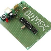
PIC-P28-USB
Description
MCU, MPU & DSP Development Tools PROTOTYPE BRD ICSP/ ICD ENABLED 28 PIN
Manufacturer
Olimex Ltd.
Datasheet
1.PIC-P28-USB.pdf
(8 pages)
Specifications of PIC-P28-USB
Processor To Be Evaluated
28 Pin PIC Devices
Interface Type
USB, ICSP
Dimensions
100 mm x 80 mm
Operating Supply Voltage
3.3 V, 5 V
Tool Type
Prototyping Board
Core Architecture
PIC
Cpu Core
PIC
Data Bus Width
8 bit
External Height
80mm
External Width
100mm
Mcu Supported Families
PIC-P28
Rohs Compliant
Yes
Lead Free Status / RoHS Status
Lead free / RoHS Compliant
Other names
1776341 52R3657


SOFTWARE:
DEMO1:
DEMO2:
DEMO3:
DEMO4:
This is demo code which blinks the LED on PIC-P28-USB board.
Note:
This is demo code which show how to read BUTTON status and to switch
the LED ON when button is pressed and LED off when the button is
depressed.
This is demo code, which show how to use the USART to send and receive
characters from host PC via USB cable.
You must program the HEX code to PIC16F876 and run the code.
If you programmed the PIC correctly when you plug USB cable on your
computer will appear “virtual” COM port. When you open Hyperterminal on
your host PC computer with 9600 bps, 8 data bit, 1 stop bit, No flow control
the PIC-P28-USB every character you type on the hyperterminal will be
printed back with “*” i.e. if you type “abc” you will receive “a*b*c*”.
This is demo code, which show how to use the EEPROM to read and write
data. Note: you must put 24LC16 EEPROM in the DIL8 socket.
PIC16F876-I/P
PIC16F876-I/P
PIC16F876-I/P
PIC16F876-I/P
LED jumper should be closed!
BLINK LED
BUTTON read
RS232 send / receive routines
EEPROM read / write routines
Related parts for PIC-P28-USB
Image
Part Number
Description
Manufacturer
Datasheet
Request
R

Part Number:
Description:
MCU, MPU & DSP Development Tools PROTOTYPE BRD FOR 28 PIN PIC
Manufacturer:
Olimex Ltd.
Datasheet:


Part Number:
Description:
MCU, MPU & DSP Development Tools PROTOTYPE BRD FOR 40 PIN PIC
Manufacturer:
Olimex Ltd.
Datasheet:

Part Number:
Description:
Daughter Cards & OEM Boards PIC-BEE XBEE RADIO INTERFACE
Manufacturer:
Gravitech
Datasheet:
Part Number:
Description:
Development Boards & Kits - PIC / DSPIC MINI PROTOTYPE BRD FOR 8 PIN PIC
Manufacturer:
Olimex Ltd.

Part Number:
Description:
MCU, MPU & DSP Development Tools PROTOTYPE BRD FOR 18 PIN PIC
Manufacturer:
Olimex Ltd.
Datasheet:

Part Number:
Description:
DEVELOPMENT BOARD FOR 18 PIN PIC MICROCONTROLLERS
Manufacturer:
Olimex Ltd.
Datasheet:
Part Number:
Description:
Development Boards & Kits - PIC / DSPIC PROTOTYPE BRD FOR PIC18F26J50
Manufacturer:
Olimex Ltd.

Part Number:
Description:
Microcontroller & Microprocessor Development Tools TCP-IP DEV BRD PIC32MX460F512
Manufacturer:
Olimex Ltd.
Datasheet:

Part Number:
Description:
Microcontroller & Microprocessor Development Tools PROTOTYPE BOARD TMS320F28027
Manufacturer:
Olimex Ltd.
Datasheet:

Part Number:
Description:
Microcontroller & Microprocessor Development Tools HDR BRD FOR LPC3131
Manufacturer:
Olimex Ltd.
Datasheet:

Part Number:
Description:
Microcontroller & Microprocessor Development Tools MP3 PLYR MOD WITH VS1002
Manufacturer:
Olimex Ltd.
Datasheet:
Part Number:
Description:
Microcontroller & Microprocessor Development Tools MP3 PLYR MOD BAT WITH VS1002
Manufacturer:
Olimex Ltd.
Datasheet: