MCBTMPM330 Keil Tools, MCBTMPM330 Datasheet
MCBTMPM330
Manufacturer Part Number
MCBTMPM330
Description
MCU, MPU & DSP Development Tools EVAL BOARD FOR TOSHIBA TMPM330x
Manufacturer
Keil Tools
Datasheet
1.MCBTMPM330.pdf
(2 pages)
Specifications of MCBTMPM330
Processor To Be Evaluated
TMPM330FDFG
Interface Type
USB, JTAG
Core
Cortex-M3
Lead Free Status / RoHS Status
Lead free / RoHS Compliant


This Quick Start Guide introduces the MCBTMPM330
board for the Toshiba TMPM330 family of Cortex-M3 based
devices. It shows how to install Keil software development
tools for ARM-based microcontrollers and run the example
projects provided.
Installing the Software
To install the evaluation version of the MDK-ARM
If the opening screen does not appear, run SETUP from the
CD root directory
Note: The first MCBTMPM330 boards shipped without a
CD-ROM. An evaluation version of MDK-ARM is available
for download from
Blinky Example
This example demonstrates the ease of downloading and
debugging an application on a target board.
It can be found at:
To use this example
Microcontroller Development Kit from a CD-ROM
Insert the CD-ROM into your PC.
Click Install Evaluation Software, then ARM Compiler (Eval
Tools)
Follow the setup program instructions
Open the Blinky.uv2 project file
Compile and link the Blinky application
Program the application into on-chip Flash ROM
C:\Keil\ARM\Boards\Keil\MCBTMPM330\Blinky
Start Vision
Project - Open
Project - Build
Flash - Download
https://www.keil.com/demo/eval/arm.htm.
Getting Started and Blinky Example
www.keil.com/mcbtmpm330
Connecting to your Target
The target is powered via your PC, through its USB port. The Keil
ULINK family of adapters connect the USB port of your PC to
the JTAG port of your target board, allowing you to download and
debug embedded programs running on your target hardware.
ULINK2 and ULINK-ME support JTAG and Serial-Wire Debug
(SWD) for debugging of ARM-based targets.
Using ULINK2
The ULINK2 Adapter connects to the MCBTMPM330 using the
20-pin ribbon cable.
Using ULINK-ME
The ULINK-ME Adapter connects directly to the 20-pin JTAG
connector on the MCBTMPM330.
Using the debugger commands, you may:
MCBTMPM330
The LEDs on the target are controlled by the potentiometer
setting. As the setting increases, the LEDs scroll faster.
Start debug mode
Single step through code
Set breakpoints
Run the application
Review variables in the watch window
Reset the device to re-run the application
Use the yellow arrow (program counter) to view the
current assembler or C statement
Quick Start Guide
Related parts for MCBTMPM330
Image
Part Number
Description
Manufacturer
Datasheet
Request
R

Part Number:
Description:
Development Boards & Kits - ARM KEIL NUVOTON EVAL BD CORTEX-M0 + ULINK-ME
Manufacturer:
Keil Tools
Datasheet:
Part Number:
Description:
Development Boards & Kits - ARM KEIL NUVOTON EVAL BD CORTEX-M0
Manufacturer:
Keil Tools
Datasheet:

Part Number:
Description:
Development Software ASSEMBLER KIT C51 uVISION IDE & TOOLS
Manufacturer:
Keil Tools

Part Number:
Description:
MCU, MPU & DSP Development Tools EVAL BOARD FOR NXP LPC1768 + ULINK2
Manufacturer:
Keil Tools

Part Number:
Description:
MCU, MPU & DSP Development Tools EVAL BOARD FOR NXP LPC1768 + ULINK-ME
Manufacturer:
Keil Tools
Part Number:
Description:
MCU, MPU & DSP Development Tools EVAL BOARD FOR NXP LPC214x + ULINK2
Manufacturer:
Keil Tools

Part Number:
Description:
MCU, MPU & DSP Development Tools EVAL BOARD FOR STM STM32E
Manufacturer:
Keil Tools
Datasheet:

Part Number:
Description:
MCU, MPU & DSP Development Tools EVAL BOARD MCBX51 8051 & 251 SBC
Manufacturer:
Keil Tools
Part Number:
Description:
MCU, MPU & DSP Development Tools EVAL BOARD FOR NXP LPC2100+ULINK2
Manufacturer:
Keil Tools

Part Number:
Description:
MCU, MPU & DSP Development Tools EVAL BOARD FOR NXP LPC247x
Manufacturer:
Keil Tools
Part Number:
Description:
MCU, MPU & DSP Development Tools EVAL BOARD FOR NXP LPC214x + ULINK-ME
Manufacturer:
Keil Tools
Part Number:
Description:
MCU, MPU & DSP Development Tools EVAL BOARD FOR NXP LPC2470+ULINK2
Manufacturer:
Keil Tools

Part Number:
Description:
MCU, MPU & DSP Development Tools EVAL BOARD FOR NXP LPC2929+ULINK2
Manufacturer:
Keil Tools
Part Number:
Description:
MCU, MPU & DSP Development Tools EVAL BOARD FOR NXP LPC213x + ULINK2
Manufacturer:
Keil Tools

Part Number:
Description:
MCU, MPU & DSP Development Tools EVAL BOARD FOR STM STR730
Manufacturer:
Keil Tools
MCBTMPM330 Summary of contents
Page 1
... ULINK2 and ULINK-ME support JTAG and Serial-Wire Debug (SWD) for debugging of ARM-based targets. Using ULINK2 The ULINK2 Adapter connects to the MCBTMPM330 using the 20-pin ribbon cable. Using ULINK-ME The ULINK-ME Adapter connects directly to the 20-pin JTAG connector on the MCBTMPM330 ...
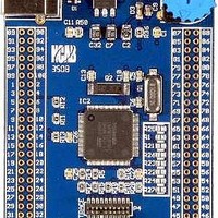
Page 2
... Logic Analyzer Window. These values change as you move the potentiometer. Prototyping with MCBTMPM330 The MCBTMPM330 routes all the peripheral ports of the TMPM330 device to a 0.1inch prototyping grid with a DIP form factor. The numbers next to the prototyping holes match the numbers of the device pins they connect to ...