BH-14e_TI-60t_TI Blackhawk, BH-14e_TI-60t_TI Datasheet - Page 2
BH-14e_TI-60t_TI
Manufacturer Part Number
BH-14e_TI-60t_TI
Description
Microcontroller Modules & Accessories Adapter Pin Converter
Manufacturer
Blackhawk
Datasheet
1.BH-14E_TI-60T_TI.pdf
(2 pages)
Specifications of BH-14e_TI-60t_TI
Product
Microcontroller Accessories
Interface Type
JTAG
Lead Free Status / RoHS Status
Lead free / RoHS Compliant


Standard 14-pin
TI JTAG Header
Connect to emulator’s
14-pin socket connector.
The pin converter (P/N: 50-ADP-14e_TI-20t_cTI-0) described here (see
figures 2 and 3) allows an emulator with the standard TI 14-pin JTAG connec-
tion to connect to the new, 20-pin compact TI (cTI) header (table 2) on a target
board. An example of this new, 20-pin cTI header can be found on the TI
DaVinci EVM board with DM6446 deivce.
Using this adapter provides backwards compatibility
to standard debug connections and does not per-
form any processing or contain any on-board logic.
It is strictly a pin converter, routing only pins 1-14,
and can be used with XDS510™ and XDS560™-
class emulators with a 14-pin socket connector.
2
Caution should be exercised in connecting these adapters to the JTAG emu-
lator and the target JTAG header. Pay special attention to the orientation and
keying and pin outs. Be careful to connect with the correct orientation.
These adapters are not intended to be hot pluggable. Unplug power from all
sources prior to connect or disconnect.
1
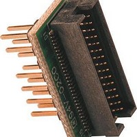
14e_TI-20t_cTI Pin Converter
Typical target board cable
connection orientation
Figure 3
Top and bottom view of 14e_TI-20t_cTI Pin Converter
(TOP)
WARNING
(pin 6 keyed)
Figure 2
(BOTTOM)
Pin
11
13
15
17
19
1
3
5
7
9
New, 20-pin Compact TI
nSRST
Name
RTCK
EMU0
EMU2
EMU4
JTAG Header
TMS
TDI
TVD
TDO
TCK
Compact Ti (cTI) 20-
pin JTAG connector
Connect this end to target
board with 20-pin cTI
header.
†
Signals are active low
Table 2
†
Pin
10
12
14
16
18
20
2
4
6
8
nTRST
Name
TDIS
EMU1
EMU3
KEY
GND
GND
GND
GND
GND
†
The 60-pin emulation connectors on
the target board and pin converters
should be labeled to identify orienta-
tion.
The “DSP” label goes towards the
DSP chip. The
identifies the side in which the trace
cable, or in this case, the emulator,
is attached.
The locations of these labels and
orientation are shown in figure 5.
The pin converter (P/N: 50-ADP-14e_TI-60t_TI-0) described here (see
figure 4) allows an emulator with the standard 14-pin JTAG connection to
connect to the new, 60-pin emulation header. An example of this new, 60-
pin header can be found on the TI C6416 DSK.
Using this adapter provides compatibility of standard debug connections and
does not perform any processing or contain any on-board logic. It is strictly a
pin converter, routing only pins 1-14, and can be used with XDS510™ and
XDS560™-class emulators with standard 14-pin socket connector. The sig-
nal definitions for the 60-pin header are show in table 3 on page 4.
Caution should be exercised in connecting these adapters to the JTAG emu-
lator and the target JTAG header. Pay special attention to the orientation and
keying and pin outs. Be careful to connect with the correct orientation.
These adapters are not intended to be hot pluggable. Unplug power from all
sources prior to connect or disconnect.
14e_TI-60t_TI Pin Converter
Standard 14-pin
TI JTAG Header
Connect to emulator’s
14-pin socket connector.
“Cable
Angled view of 14e_TI-60t_TI Pin Converter
Entry” label
WARNING
Figure 4
Typical target board and emulator
cable connection orientation
TI 60-pin Emulation
connector
Connect this end to target
board with a 60-pin emulation
header.
Figure 5
2
3
Related parts for BH-14e_TI-60t_TI
Image
Part Number
Description
Manufacturer
Datasheet
Request
R

Part Number:
Description:
Microcontroller Modules & Accessories Adapter Pin Converter
Manufacturer:
Blackhawk
Datasheet:

Part Number:
Description:
MCU, MPU & DSP Development Tools USB560M Emulator
Manufacturer:
Blackhawk
Datasheet:

Part Number:
Description:
MCU, MPU & DSP Development Tools USB560BP Emulator
Manufacturer:
Blackhawk
Datasheet:

Part Number:
Description:
Ethernet Modules & Development Tools Remote Software Pro
Manufacturer:
Blackhawk
Datasheet:

Part Number:
Description:
MCU, MPU & DSP Development Tools USB2000 Controller
Manufacturer:
Blackhawk
Datasheet:

Part Number:
Description:
MCU, MPU & DSP Development Tools USB100 JTAG CONTROLR VERSION 2D
Manufacturer:
Blackhawk

Part Number:
Description:
MCU, MPU & DSP Development Tools USB510L Emulator
Manufacturer:
Blackhawk
Datasheet:

Part Number:
Description:
MCU, MPU & DSP Development Tools PCI560 Emulator
Manufacturer:
Blackhawk
Datasheet:

Part Number:
Description:
MCU, MPU & DSP Development Tools LAN560 Emulator
Manufacturer:
Blackhawk
Datasheet:

Part Number:
Description:
MCU, MPU & DSP Development Tools XDS560 Trace System
Manufacturer:
Blackhawk
Datasheet:

Part Number:
Description:
Microcontroller Modules & Accessories BH Isolation Adapter 14-pin
Manufacturer:
Blackhawk
Datasheet:

Part Number:
Description:
Microcontroller Modules & Accessories Adapter Pin Converter
Manufacturer:
Blackhawk
Datasheet:

Part Number:
Description:
Microcontroller Modules & Accessories Adapter Pin Saver
Manufacturer:
Blackhawk

Part Number:
Description:
Microcontroller Modules & Accessories Adapter Pin Converter
Manufacturer:
Blackhawk

Part Number:
Description:
Microcontroller Modules & Accessories Adapter Pin Converter
Manufacturer:
Blackhawk
Datasheet: