BH-20e_cTI-14t_TI Blackhawk, BH-20e_cTI-14t_TI Datasheet - Page 2
BH-20e_cTI-14t_TI
Manufacturer Part Number
BH-20e_cTI-14t_TI
Description
Microcontroller Modules & Accessories Adapter Pin Converter
Manufacturer
Blackhawk
Datasheet
1.BH-20E_CTI-14T_TI.pdf
(2 pages)
Specifications of BH-20e_cTI-14t_TI
Product
Microcontroller Accessories
Interface Type
JTAG
Lead Free Status / RoHS Status
Lead free / RoHS Compliant


The
tor cable with a 20-pin cTI JTAG connection to a target board with 20
pin MultiICE connector.
2
1
1. Make sure the target is not powered when connecting!
2. Connect the 20 pin Male connector to your cTI emulator.
3. Connect the 20 pin Female socket to your target ARM.
Caution should be exercised in connecting this adapter to the JTAG
emulator and the target JTAG header. Pay special attention to the
orientation and keying and pin outs. Be careful to connect with the
correct orientation. This adapter is not intended to be hot pluggable.
Unplug power from all sources prior to connect or disconnect.
Emulator Connection:
20 pin cTI male header
(0.050” x 0.100”)
FIGURE 1—Typical target board cable
20e_cTI-20t_ARM
20e_cTI-20t_ARM Pin Converter
connection orientation
Pin Converter is designed to attach an emula-
WARNING
20-Pin Target ARM Header Pin out
Pin
11
13
15
17
19
1
3
5
7
9
nTRST
nSRST
Name
RTCK
VDD
TDI
TMS
TCK
TDO
NC
NC
Target Board Connection:
20 pin female socket header
(0.100” x 0.100”)
†
†
†
Signals are active low
Pin
10
12
14
16
18
20
2
4
6
8
Name
VDD
GND
GND
GND
GND
GND
GND
GND
GND
GND
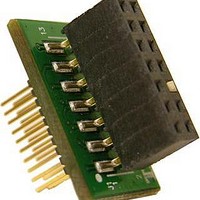
The
tor cable with a 20-pin cTI JTAG connection to a target board with 14
pin connector with pin 6 keyed.
1. Make sure the target is not powered when connecting!
2. Connect the 20 pin Male connector to your cTI emulator.
3. Connect the 14 pin Female socket to your target TI.
Caution should be exercised in connecting this adapter to the JTAG
emulator and the target JTAG header. Pay special attention to the
orientation and keying and pin outs. Be careful to connect with the
correct orientation. This adapter is not intended to be hot pluggable.
Unplug power from all sources prior to connect or disconnect.
Emulator Connection:
20 pin cTI male header
(0.050” x 0.100”)
FIGURE 1—Typical target board cable
20e_cTI-14t_TI
20e_cTI-14t_TI Pin Converter
connection orientation
Pin Converter is designed to attach an emula-
WARNING
TI 14-Pin Target Header Pin out
Pin
11
13
1
3
5
7
9
Name
RTCK
TCLK
EMU0
TMS
TDI
TVD
TDO
Target Board Connection:
14 pin female socket header -
pin 6 keyed. (0.100” x 0.100”)
†
Signals are active low
Pin
10
12
14
2
4
6
8
Name
nTRST
EMU1
GND
KEY
GND
GND
GND
†
2
3
Related parts for BH-20e_cTI-14t_TI
Image
Part Number
Description
Manufacturer
Datasheet
Request
R

Part Number:
Description:
Microcontroller Modules & Accessories Adapter Pin Converter
Manufacturer:
Blackhawk
Datasheet:

Part Number:
Description:
Microcontroller Modules & Accessories Adapter Pin Converter
Manufacturer:
Blackhawk
Datasheet:

Part Number:
Description:
MCU, MPU & DSP Development Tools USB560M Emulator
Manufacturer:
Blackhawk
Datasheet:

Part Number:
Description:
MCU, MPU & DSP Development Tools USB560BP Emulator
Manufacturer:
Blackhawk
Datasheet:

Part Number:
Description:
Ethernet Modules & Development Tools Remote Software Pro
Manufacturer:
Blackhawk
Datasheet:

Part Number:
Description:
MCU, MPU & DSP Development Tools USB2000 Controller
Manufacturer:
Blackhawk
Datasheet:

Part Number:
Description:
MCU, MPU & DSP Development Tools USB100 JTAG CONTROLR VERSION 2D
Manufacturer:
Blackhawk

Part Number:
Description:
MCU, MPU & DSP Development Tools USB510L Emulator
Manufacturer:
Blackhawk
Datasheet:

Part Number:
Description:
MCU, MPU & DSP Development Tools PCI560 Emulator
Manufacturer:
Blackhawk
Datasheet:

Part Number:
Description:
MCU, MPU & DSP Development Tools LAN560 Emulator
Manufacturer:
Blackhawk
Datasheet:

Part Number:
Description:
MCU, MPU & DSP Development Tools XDS560 Trace System
Manufacturer:
Blackhawk
Datasheet:

Part Number:
Description:
Microcontroller Modules & Accessories BH Isolation Adapter 14-pin
Manufacturer:
Blackhawk
Datasheet:

Part Number:
Description:
Microcontroller Modules & Accessories Adapter Pin Converter
Manufacturer:
Blackhawk
Datasheet:

Part Number:
Description:
Microcontroller Modules & Accessories Adapter Pin Converter
Manufacturer:
Blackhawk
Datasheet:

Part Number:
Description:
Microcontroller Modules & Accessories Adapter Pin Saver
Manufacturer:
Blackhawk