ECG008B-PCB TriQuint, ECG008B-PCB Datasheet - Page 2
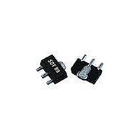
ECG008B-PCB
Manufacturer Part Number
ECG008B-PCB
Description
WiFi / 802.11 Modules & Development Tools 700-2400MHz Eval Brd 15dB Gain
Manufacturer
TriQuint
Datasheet
1.ECG008B-PCB.pdf
(4 pages)
Specifications of ECG008B-PCB
Wireless Frequency
700 MHz to 2.4 GHz
Operating Voltage
7.3 VDC
Operating Temperature Range
- 40 C to + 85 C
For Use With/related Products
ECG008B
Lead Free Status / RoHS Status
Lead free / RoHS Compliant
Other names
1067363
Available stocks
Company
Part Number
Manufacturer
Quantity
Price
Company:

Part Number:
ECG008B-PCB
Manufacturer:
WJ
Quantity:
12 800
Part Number:
ECG008B-PCB
Manufacturer:
WJ
Quantity:
20 000


WJ Communications, Inc • Phone 1-800-WJ1-4401 • FAX: 408-577-6621 • e-mail: sales@wj.com • Web site: www.wj.com, www.TriQuint.com
1. Test conditions: T = 25º C, Supply Voltage = +9 V, Device Voltage = 7.3 V, Rbias = 14 Ω, Icc = 120 mA typical, 50 Ω System.
2. 3OIP measured with two tones at an output power of +9 dBm/tone separated by 1 MHz. The suppression on the largest IM3 product is used to calculate the 3OIP using a 2:1 rule.
3. Data is shown as device performance only. Actual implementation for the desired frequency band will be determined by external components shown in the application circuit. The performance data does not
account for losses attributed to recommended input and output series resistances shown in the application circuit on page 3.
45
40
35
30
25
20
18
16
14
12
10
500
500
Freq (MHz)
1000
1500
2000
2500
3000
3500
4000
4500
5000
5500
6000
500
ECG008
InGaP HBT Gain Block
50
1000
1000
Gain vs. Frequency
+25°C
OIP3 vs. Frequency
+25°C
Frequency (MHz)
Frequency (MHz)
1500
1500
Frequency
S21
S11
S22
Output P1dB
Output IP3
Noise Figure
-24.87
-26.14
-28.46
-30.86
-28.14
-23.15
-18.78
-15.39
-12.91
-10.59
S11 (dB)
-8.44
-6.76
-5.43
-40°C
-40°C
2000
2000
Device S-parameters are available for download off of the website at: http://www.wj.com
+85°C
+85°C
S-Parameters (V
2500
2500
-178.22
-144.76
-137.68
-150.37
-171.26
176.05
167.68
166.94
161.38
132.87
105.27
S11 (ang)
80.71
61.63
Typical Device RF Performance
MHz
dBm
dBm
dB
dB
dB
dB
Supply Bias = +9 V, R
3000
3000
device
+24.5
+41.6
14.8
100
-25
-20
4.9
4.5
3.5
2.5
-10
-15
-20
-25
-30
-35
-40
S21 (dB)
14.88
14.71
14.60
14.39
14.30
14.20
14.30
14.48
14.65
14.51
14.04
13.17
12.10
= +7.3 V, I
-5
5
4
3
2
0
500
0
+24.3
14.7
500
+41
-26
-19
4.7
Noise Figure vs. Frequency
1
S11, S22 vs. Frequency
CC
= 120 mA, T = 25°C, calibrated to device leads)
Frequency (GHz)
1000
177.77
161.26
142.99
125.46
108.38
S21 (ang)
-31.25
-50.89
91.08
74.41
56.29
35.57
13.60
-8.75
Frequency (MHz)
2
-28.5
S22
14.6
+24
+40
900
-17
4.6
bias
3
= 14 Ω, I
+23.2
1900
14.3
+37
1500
-28
-13
4.7
-18.94
-18.94
-19.02
-18.94
-18.86
-18.64
-18.20
-17.52
-16.85
-16.36
-16.20
-16.26
-16.59
S12 (dB)
4
S11
cc
+22.8
5
2140
14.3
+36
-25
-13
4.9
= 120 mA
2000
6
Specifications and information are subject to change without notice
S12 (ang)
-11.44
-16.56
-21.00
-25.54
-29.98
-36.74
-45.50
-56.53
-68.74
-81.52
-93.75
-1.51
-5.99
+21.8
-23.2
2400
14.2
+34
-12
5.2
140
120
100
80
60
40
20
30
25
20
15
10
0
(3)
0.0
500
+25°C
+17.3
3500
-15.4
14.5
-7.9
1000
-20.41
-19.43
-17.47
-15.40
-13.40
-11.63
2.0
S22 (dB)
-9.65
-7.83
-6.06
-4.68
-3.62
-2.87
-2.41
P1dB vs. Frequency
+25°C
Frequency (MHz)
Vde vs. Icc
1500
5800
12.4
4.0
-2.7
Vde (V)
-6
-40°C
-116.18
-133.34
-151.20
-171.17
165.56
141.33
117.07
S22 (ang)
-39.76
-72.27
-95.62
94.30
73.89
-4.20
2000
6.0
Page 2 of 4 January 2008
+85°C
2500
8.0
3000
10.0
Related parts for ECG008B-PCB
Image
Part Number
Description
Manufacturer
Datasheet
Request
R

Part Number:
Description:
RF Amplifier DC-4 GHz +24dBm P1dB@1 GHz
Manufacturer:
TriQuint
Datasheet:

Part Number:
Description:
Manufacturer:
TriQuint
Datasheet: