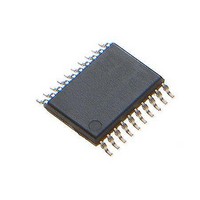
MAX1441GUP/V+ Maxim Integrated Products, MAX1441GUP/V+ Datasheet - Page 23

MAX1441GUP/V+
Manufacturer Part Number
MAX1441GUP/V+
Description
Touch Screen Converters & Controllers PROXIMITY SENSR el Proximity and Tou
Manufacturer
Maxim Integrated Products
Datasheet
1.MAX1441GUPV.pdf
(41 pages)
Specifications of MAX1441GUP/V+
Lead Free Status / RoHS Status
Lead free / RoHS Compliant
Table 11. Special-Function Register Bit Description (continued)
EIE0 (02h, 00h)
Initialization
Read/Write Access
EIE0[2:0]–EX[2:0]
EIE0[7:3]
EIES0 (03h, 00h)
Initialization
Read/Write Access
EIES0[2:0]–IT[2:0]
EIS0[7:3]
TCON (04h, 00h)
Initialization
Read/Write Access
TCON[2:0]–TPSS[2:0]
TCON.3–TCLK
TCON.4–TMREN
TCON.5–TVALID
TCON.6–TMRIF
TCON.7–TMRIE
REGISTER
Automotive, Two-Channel Proximity and
External Interrupt Enable 0 Register (8-Bit Register)
This register is cleared to 00h on all forms of reset.
Unrestricted read/write.
Enable External Interrupt Bits [2:0]. Setting any of these bits to 1 enables the corresponding external
interrupt, INTx. Clearing any of the bits to 0 disables the corresponding interrupt function.
Reserved. Read returns 0.
External Interrupt Edge Select 0 Register (8-Bit Register)
This register is cleared to 00h on all forms of reset.
Unrestricted read/write.
Edge Select for External Interrupt Bits [2:0]:
ITx = 0 – External Interrupt INTx is positive edge triggered.
ITx = 1 – External Interrupt INTx is negative edge triggered.
Reserved. Read returns 0.
Timer Control Register (8-Bit Register)
This register is cleared to 00h on all forms of reset.
Unrestricted read. Write is unrestricted, unless otherwise stated in the following bit description.
Timer Prescaler Select Bits [2:0]. The following bits select the prescaler value that apply to the select
source clock.
These bits can only be written to when the timer is disabled (TMREN = 0).
Timer Clock Select. This bit selects the clock source used by the Timer. When this bit is cleared to 0,
the system clock is used as the clock source. When this bit is set to 1, the 32kHz is used.
This bit can only be written to when the timer is disabled (TMREN = 0).
Timer Enable. Setting this bit to 1 enables the Timer. Clearing this bit halts the Timer. The Timer contin-
ues to run in Stop mode if TMREN = 1.
Timer Value Valid. This bit indicates whether TCNT returns the valid value when 32kHz is selected as
the clock source. When this bit is set to 1, TCNT returns the valid value. When this bit is cleared to 0,
TCNT returns 0000h.
This bit has no meaning when the system clock is used as a clock source. In this case, TCNT always
returns valid value.
Timer Interrupt Flag. This bit is set to 1 when the Timer count matches the timer frequency value. It is
cleared either by software or a reset. A 0 on this bit indicates no Timer overflow has been detected.
Timer Interrupt Enable. Setting this bit to 1 enables the Timer interrupt. Clearing this bit to 0 disables
the Timer interrupt.
TPSS[2:0]
000
001
010
011
100
101
110
111
DESCRIPTION
Touch Sensor
PRESCALE VALUE
/1024
/2048
/256
/512
/16
/64
/1
/4
23


