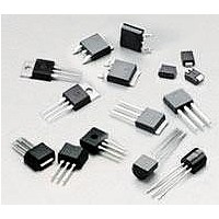
L401E3 Littelfuse Inc, L401E3 Datasheet - Page 4

L401E3
Manufacturer Part Number
L401E3
Description
Triacs 400V 1A Sensing 3-3-3-3mA
Manufacturer
Littelfuse Inc
Specifications of L401E3
Rated Repetitive Off-state Voltage Vdrm
400 V
Breakover Current Ibo Max
20 A
On-state Rms Current (it Rms)
1 A
Off-state Leakage Current @ Vdrm Idrm
0.01 mA
Gate Trigger Voltage (vgt)
2 V
Gate Trigger Current (igt)
1 A
Holding Current (ih Max)
5 mA
Forward Voltage Drop
1.6 V
Mounting Style
Through Hole
Package / Case
TO-92
Maximum Operating Temperature
+ 110 C
Minimum Operating Temperature
- 65 C
Repetitive Peak Forward Blocking Voltage
400 V (Min)
Channel Type
B-Directional
Current, Gate Trigger
3 A
Current, On-state, Average, Maximum
1 A
Current, On-state, Rms, Maximum
1 A
Package Type
Compak
Power Dissipation
0.2 W
Resistance, Thermal, Junction To Case
50 °C/W
Temperature, Operating, Maximum
+110 °C
Temperature, Operating, Minimum
–65 °C
Thermal Resistance, Junction To Ambient
95 °C/W
Voltage, Drain To Gate
0.2 V
Voltage, Reverse, Peak, Maximum
400 V
Lead Free Status / RoHS Status
Lead free / RoHS Compliant
Available stocks
Company
Part Number
Manufacturer
Quantity
Price
Company:
Part Number:
L401E3
Manufacturer:
Littelfus
Quantity:
21 000
Lx01Ex & LxNx & Qx01Ex & QxNx Series
Figure 3: Normalized DC Holding Current
Figure 5: Power Dissipation (Typical)
Figure 7: Maximum Allowable Ambient Temperature
4.0
3.0
2.0
1.0
0.0
120
100
80
60
40
20
1.0
0.0
1.5
0.5
-65
0.0
0
vs. Junction Temperature
vs. RMS On-State Current
vs. On-State Current
-40
0.1
CURRENT WAVE FORM: Sinusoidal
LOAD: Resistive or Inductive
CONDUCTION ANGLE: 360°
0.25
-15
RMS On-State Current [I
RMS On-State Current (I
0.2
Junction Temperature (Tj) - ºC
10
0.5
0.3
35
CURRENT WAVEFORM: Sinusoidal
LOAD: Resistive or Inductive
CONDUCTION ANGLE: 360º
FREE AIR RATING - NO HEATSINK
0.4
60
0.75
T(RMS)
T(RMS)
] - AMPS
) - Amps
0.5
85
1 Amp Sensitive & Standard Triacs
Teccor
1.0
110
0.6
125
®
1.25
0.7
Revised: July 9, 2008
brand Thyristors
36
Figure 4: Normalized DC Gate Trigger Voltage for
Figure 6: Maximum Allowable Case Temperature
Figure 8: On-State Current vs. On-State Voltage
2.0
1.5
1.0
0.5
0.0
130
120
110
100
90
80
70
60
50
-65
8
7
6
5
4
3
2
1
0
0
0.6
All Quadrants vs. Junction Temperature
vs. On-State Current
Lx01Ex / LxNx
(Typical)
-40
Positive or Negative Instantaneous On-State Voltage
0.2
0.8
RMS On-State Current [I
-15
Junction Temperature (T
Please refer to http://www.littelfuse.com for current information.
Please refer to http://www.littelfuse.com for current information.
0.4
1.0
10
Qx01Ex /QxNx
Specifications are subject to change without notice.
Specifications are subject to change without notice.
(V
T
T
35
) - Volts
0.6
C
1.2
= 25ºC
CURRENT WAVE FORM: Sinusoidal
LOAD: Resistive or Inductive
CONDUCTION ANGLE: 360º
CASE TEMPERATURE: Measured as shown
on Dimensional Drawing
T(RMS)
60
] - AMPS
j
) - ºC
1.4
0.8
85
1.6
©2008 Littelfuse, Inc.
1
110
1.8
125
1.2


