SiHF16N50C-E3 Vishay, SiHF16N50C-E3 Datasheet - Page 2
SiHF16N50C-E3
Manufacturer Part Number
SiHF16N50C-E3
Description
MOSFET Power N-Channel 500V
Manufacturer
Vishay
Datasheet
1.SIHP16N50C-E3.pdf
(8 pages)
Specifications of SiHF16N50C-E3
Transistor Polarity
N-Channel
Gate Charge Qg
68 nC
Minimum Operating Temperature
- 55 C
Configuration
Single
Forward Transconductance Gfs (max / Min)
3 S
Drain-source Breakdown Voltage
500 V
Continuous Drain Current
16 A
Power Dissipation
38 W
Maximum Operating Temperature
+ 150 C
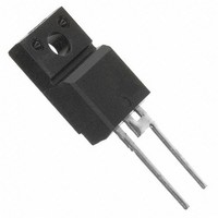
Mounting Style
Through Hole
Package / Case
TO-220
Drain Source Voltage Vds
500V
On Resistance Rds(on)
0.31ohm
Rds(on) Test Voltage Vgs
10V
Voltage Vgs Max
30V
Operating Temperature Range
-55°C To +150°C
Lead Free Status / RoHS Status
Lead free / RoHS Compliant
Lead Free Status / RoHS Status
Lead free / RoHS Compliant, Lead free / RoHS Compliant
Available stocks
Company
Part Number
Manufacturer
Quantity
Price


SiHP16N50C, SiHB16N50C, SiHF16N50C
Vishay Siliconix
Note
a. When mounted on 1" square PCB (FR-4 or G-10 material).
Note
• The information shown here is a preliminary product proposal, not a commercial product data sheet. Vishay Siliconix is not committed to
www.vishay.com
2
THERMAL RESISTANCE RATINGS
PARAMETER
Maximum Junction-to-Ambient
Maximum Junction-to-Case (Drain)
Junction-to-Ambient (PCB mount)
SPECIFICATIONS T
PARAMETER
Static
Drain-Source Breakdown Voltage
V
Gate-Source Threshold Voltage (N)
Gate-Source Leakage
Zero Gate Voltage Drain Current
Drain-Source On-State Resistance
Forward Transconductance
Dynamic
Input Capacitance
Output Capacitance
Reverse Transfer Capacitance
Total Gate Charge
Gate-Source Charge
Gate-Drain Charge
Turn-On Delay Time
Rise Time
Turn-Off Delay Time
Fall Time
Gate Input Resistance
Drain-Source Body Diode Characteristics
Continuous Source-Drain Diode Current
Pulsed Diode Forward Current
Body Diode Voltage
Body Diode Reverse Recovery Time
Body Diode Reverse Recovery Charge
Body Diode Reverse Recovery Current
produce this or any similar product. This information should not be used for design purposes, nor construed as an offer to furnish or sell
such products.
DS
Temperature Coefficient
J
a
= 25 °C, unless otherwise noted
a
SYMBOL
SYMBOL
ΔV
R
V
R
R
R
t
t
C
I
I
I
C
V
DS(on)
C
Q
Q
V
GS(th)
d(on)
d(off)
I
RRM
GSS
DSS
Q
DS
g
Q
R
thJA
thJC
thJA
SM
t
I
t
t
DS
oss
SD
iss
rss
S
rr
fs
gs
gd
r
f
g
rr
g
/T
J
TO220-AB D
MOSFET symbol
showing the
integral reverse
p - n junction diode
V
V
V
T
GS
GS
DS
J
T
Reference to 25 °C, I
= 25 °C, I
J
= 10 V
= 10 V
= 400 V, V
= 25 °C, I
V
V
V
R
V
f = 1 MHz, open drain
TEST CONDITIONS
DS
DD
DS
V
GS
g
DS
0.5
= 9.1 Ω, V
62
40
2
= V
= 500 V, V
= 250 V, I
PAK (TO-263)
= 0 V, I
V
f = 1.0 MHz
V
= 50 V, I
F
GS
V
V
DS
= I
GS
GS
S
R
GS
= ± 30 V
= 10 A, V
= 20 V
I
, I
= 25 V,
S
D
= 0 V,
, dI/dt = 100 A/μs,
= 0 V, T
D
D
= 16 A, V
GS
= 250 μA
= 250 μA
D
D
GS
= 16 A,
= 3 A
= 10 V
I
D
= 0 V
D
J
GS
= 1 mA
= 8 A
= 125 °C
G
DS
= 0 V
= 400 V
TO-220 FULLPAK
D
S
3.3
65
-
MIN.
500
3.0
-
-
-
-
-
-
-
-
-
-
-
-
-
-
-
-
-
-
-
-
-
-
-
S10-0811-Rev. A, 12-Apr-10
Document Number: 91401
TYP.
1900
0.31
230
156
555
0.6
1.6
5.5
24
45
18
22
27
29
31
18
3
-
-
-
-
-
-
-
-
MAX.
± 100
0.38
250
5.0
1.8
50
68
16
30
-
-
-
-
-
-
-
-
-
-
-
-
-
-
-
-
UNIT
°C/W
UNIT
V/°C
nC
μC
nA
μA
pF
ns
ns
Ω
Ω
V
V
S
A
V
A
Related parts for SiHF16N50C-E3
Image
Part Number
Description
Manufacturer
Datasheet
Request
R

Part Number:
Description:
357-036-542-201 CARDEDGE 36POS DL .156 BLK LOPRO
Manufacturer:
Vishay
Datasheet:
Part Number:
Description:
357-036-542-201 CARDEDGE 36POS DL .156 BLK LOPRO
Manufacturer:
Vishay
Datasheet:
Part Number:
Description:
357-036-542-201 CARDEDGE 36POS DL .156 BLK LOPRO
Manufacturer:
Vishay
Datasheet:
Part Number:
Description:
357-036-542-201 CARDEDGE 36POS DL .156 BLK LOPRO
Manufacturer:
Vishay
Datasheet:
Part Number:
Description:
357-036-542-201 CARDEDGE 36POS DL .156 BLK LOPRO
Manufacturer:
Vishay
Datasheet:
Part Number:
Description:
357-036-542-201 CARDEDGE 36POS DL .156 BLK LOPRO
Manufacturer:
Vishay
Datasheet:
Part Number:
Description:
357-036-542-201 CARDEDGE 36POS DL .156 BLK LOPRO
Manufacturer:
Vishay
Datasheet:
Part Number:
Description:
357-036-542-201 CARDEDGE 36POS DL .156 BLK LOPRO
Manufacturer:
Vishay
Datasheet:
Part Number:
Description:
357-036-542-201 CARDEDGE 36POS DL .156 BLK LOPRO
Manufacturer:
Vishay
Datasheet:
Part Number:
Description:
357-036-542-201 CARDEDGE 36POS DL .156 BLK LOPRO
Manufacturer:
Vishay
Datasheet:
Part Number:
Description:
357-036-542-201 CARDEDGE 36POS DL .156 BLK LOPRO
Manufacturer:
Vishay
Datasheet:
Part Number:
Description:
357-036-542-201 CARDEDGE 36POS DL .156 BLK LOPRO
Manufacturer:
Vishay
Datasheet:
Part Number:
Description:
357-036-542-201 CARDEDGE 36POS DL .156 BLK LOPRO
Manufacturer:
Vishay
Datasheet:
Part Number:
Description:
357-036-542-201 CARDEDGE 36POS DL .156 BLK LOPRO
Manufacturer:
Vishay
Datasheet:
Part Number:
Description:
357-036-542-201 CARDEDGE 36POS DL .156 BLK LOPRO
Manufacturer:
Vishay
Datasheet: