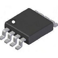
DMP4050SSD-13 Diodes Inc, DMP4050SSD-13 Datasheet - Page 2

DMP4050SSD-13
Manufacturer Part Number
DMP4050SSD-13
Description
MOSFET Small Signal MOSFET,P-CHANNEL -40V, -4.1A,-5.2A
Manufacturer
Diodes Inc
Datasheet
1.DMP4050SSD-13.pdf
(8 pages)
Specifications of DMP4050SSD-13
Minimum Operating Temperature
- 55 C
Configuration
Dual
Transistor Polarity
P-Channel
Resistance Drain-source Rds (on)
0.038 Ohms
Gate Charge Qg
6.9 nC
Forward Transconductance Gfs (max / Min)
14 S
Drain-source Breakdown Voltage
- 40 V
Gate-source Breakdown Voltage
20 V
Continuous Drain Current
- 4 A
Power Dissipation
1.25 W
Maximum Operating Temperature
+ 150 C
Mounting Style
SMD/SMT
Package / Case
SOIC-8
Lead Free Status / RoHS Status
Lead free / RoHS Compliant
Lead Free Status / RoHS Status
Lead free / RoHS Compliant
Available stocks
Company
Part Number
Manufacturer
Quantity
Price
Part Number:
DMP4050SSD-13
Manufacturer:
DIODES/美台
Quantity:
20 000
Part Number:
DMP4050SSD-13-F
Manufacturer:
DIODES/美台
Quantity:
20 000
Thermal Characteristics
Maximum Ratings
Drain-Source voltage
Gate-Source voltage
Continuous Drain current
Pulsed Drain current
Continuous Source current (Body diode)
Pulsed Source current (Body diode)
Power dissipation
Linear derating factor
Thermal Resistance, Junction to Ambient
Thermal Resistance, Junction to Lead
Operating and storage temperature range
Notes:
DMP4050SSD
Document Number DS32107 Rev 2 - 2
2. AEC-Q101 V
3. For a device surface mounted on 25mm x 25mm x 1.6mm FR4 PCB with high coverage of single sided 1oz copper, in still air conditions; the device is
4. Same as note (3), except the device is measured at t ≤ 10 sec.
5. Same as note (3), except the device is pulsed with D = 0.02 and pulse width 300µs. The pulse current is limited by the maximum junction temperature.
6. For a dual device with one active die.
7. For a device with two active die running at equal power.
8. Thermal resistance from junction to solder-point (at the end of the drain lead).
measured when operating in a steady-state condition.
GS
maximum is ±16V.
Characteristic
Characteristic
@T
V
V
GS
GS
A
= 25°C unless otherwise specified
= 10V
= 10V
@T
A
= 25°C unless otherwise specified
(Note 2)
(Notes 4 & 6)
T
(Notes 3 & 6)
(Notes 5 & 6)
(Notes 4 & 6)
(Notes 5 & 6)
A
(Notes 3 & 6)
(Notes 3 & 7)
(Notes 4 & 6)
(Notes 3 & 6)
(Notes 3 & 7)
(Notes 4 & 6)
(Notes 6 & 8)
= 70°C (Notes 4 & 6)
www.diodes.com
2 of 8
Symbol
T
Symbol
J
V
R
R
V
, T
I
I
P
DSS
I
DM
SM
I
θ JA
GS
θ JL
D
S
D
STG
Diodes Incorporated
A Product Line of
-55 to 150
Value
Value
-20.0
-20.0
1.25
10.0
14.3
2.14
17.2
-5.2
-4.2
-4.0
-3.2
±20
100
-40
1.8
70
58
53
DMP4050SSD
© Diodes Incorporated
November 2010
mW/°C
°C/W
Unit
Unit
°C
W
V
V
A
A
A
A


