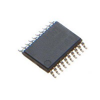
73M1906B-IM/F Maxim Integrated Products, 73M1906B-IM/F Datasheet - Page 3

73M1906B-IM/F
Manufacturer Part Number
73M1906B-IM/F
Description
Interface - Specialized DAA-FXO VolP SYSTEM HOST SIDE
Manufacturer
Maxim Integrated Products
Type
MicroDAA with PCM Highwayr
Datasheet
1.73M1866B-KEYCHN.pdf
(88 pages)
Specifications of 73M1906B-IM/F
Operating Supply Voltage
3.3 V
Maximum Operating Temperature
+ 85 C
Minimum Operating Temperature
- 40 C
Mounting Style
SMD/SMT
Package / Case
TSSOP-20
Lead Free Status / RoHS Status
Lead free / RoHS Compliant
Available stocks
Company
Part Number
Manufacturer
Quantity
Price
Company:
Part Number:
73M1906B-IM/F
Manufacturer:
Maxim
Quantity:
649
DS_1x66B_001
9
10
11
12
13
14
15
16
Revision History .................................................................................................................................. 88
Rev. 1.6
8.5
8.6
8.7
8.8
Barrier Information ...................................................................................................................... 60
9.1
9.2
9.3
9.4
9.5
9.6
9.7
Configurable Direct Access Arrangement (DAA) ....................................................................... 64
10.1 Pulse Dialing ......................................................................................................................... 64
10.2 DC Termination ..................................................................................................................... 64
10.3 AC Termination ..................................................................................................................... 66
10.4 Billing Tone Rejection ........................................................................................................... 67
10.5 Trans-Hybrid Cancellation ..................................................................................................... 68
10.6 Direct Access Arrangement Control Functions ....................................................................... 68
10.7 International Register Settings Table for DC and AC Terminations ........................................ 72
Line Sensing and Status ............................................................................................................. 73
11.1 Auxiliary A/D Converter ......................................................................................................... 73
11.2 Ring Detection ...................................................................................................................... 73
11.3 Line In Use Detection (LIU) ................................................................................................... 73
11.4 Parallel Pick Up (PPU) .......................................................................................................... 73
11.5 Polarity Reversal Detection ................................................................................................... 73
11.6 Off-hook Detection of Caller ID Type II .................................................................................. 73
11.7 Voltage and Current Detection .............................................................................................. 74
11.8 Under Voltage Detection (UVD) ............................................................................................. 74
11.9 Over Voltage Detection (OVD) .............................................................................................. 74
11.10 AC Signal Overload Detection ............................................................................................. 74
11.11 Over Current Detection (OID) .............................................................................................. 74
11.12 Line Sensing Control Functions........................................................................................... 75
Loopback and Testing Modes ..................................................................................................... 78
Performance ................................................................................................................................ 80
13.1 Transmit................................................................................................................................ 80
13.2 Receive................................................................................................................................. 82
Package Layout ........................................................................................................................... 85
Ordering Information ................................................................................................................... 87
Contact Information ..................................................................................................................... 87
Transmit and Receive Levels ................................................................................................ 48
Transmit Path Signal Processing ........................................................................................... 49
Receive Path Signal Processing ............................................................................................ 50
PCM Control Functions ......................................................................................................... 52
Isolation Barrier ..................................................................................................................... 60
Barrier Powered Options ....................................................................................................... 60
Synchronization of the Barrier ............................................................................................... 60
Auto-Poll ............................................................................................................................... 61
Barrier Control Functions ...................................................................................................... 61
Line-Side Device Operating Modes ....................................................................................... 63
Fail-Safe Operation of Line-Side Device ................................................................................ 63
8.5.1 A-Law........................................................................................................................ 48
8.5.2 μ-Law ........................................................................................................................ 48
8.5.3 Transmit and Receive Level Control .......................................................................... 48
8.6.1 General Description ................................................................................................... 49
8.6.2 Total Transmit Path Response................................................................................... 49
8.6.3 73M1x66B Transmit Spectrum................................................................................... 50
8.7.1 General Description ................................................................................................... 50
8.7.2 Total Receive Path Response.................................................................................... 51
8.7.3 Receiver DC Offset Subtraction ................................................................................. 51
8.8.1 Transmit and Receive Level Control .......................................................................... 57
8.8.2 Time Slot Assignment Example ................................................................................. 59
9.2.1 Barrier Powered Operation ........................................................................................ 60
9.2.2 Line Powered Operation ............................................................................................ 60
73M1866B/73M1966B Data Sheet
3


