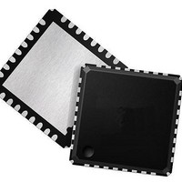
73M1916-IVT/F Maxim Integrated Products, 73M1916-IVT/F Datasheet - Page 75

73M1916-IVT/F
Manufacturer Part Number
73M1916-IVT/F
Description
Interface - Specialized DAA-FXO VolP SYSTEM LN SIDE
Manufacturer
Maxim Integrated Products
Type
MicroDAA with PCM Highwayr
Datasheet
1.73M1866B-KEYCHN.pdf
(88 pages)
Specifications of 73M1916-IVT/F
Operating Supply Voltage
3.3 V
Maximum Operating Temperature
+ 85 C
Minimum Operating Temperature
- 40 C
Mounting Style
SMD/SMT
Package / Case
QFN-32
Lead Free Status / RoHS Status
Lead free / RoHS Compliant
Available stocks
Company
Part Number
Manufacturer
Quantity
Price
Company:
Part Number:
73M1916-IVT/F
Manufacturer:
Maxim
Quantity:
1 995
DS_1x66B_001
11.12 Line Sensing Control Functions
These registers contain control information to set up and use the 73M1x66B line sensing functions.
Rev. 1.6
Function
Mnemonic
CIDM
RXBST
ENRGDT
RGDT
RGMON
RGTH
Register
Location
0x14[3]
0x0E[1:0]
0x15[4]
0x05[0]
0x03[0]
0x03[3]
Type
WO
W
W
W
R
R
Table 40: Line Sensing Control Functions
Caller ID Mode
0 = Disable Caller ID Mode. (Default)
1 = Enables Caller ID Mode by coupling the signal from the RGN/RGP
pins to the PCM DX pins in the appropriate PCM codec format. A 20 dB
gain boost is included in the signal path. The RXBST bit should also be
set to allow the total nominal gain of 40 dB in the Caller ID path. The
normal signal path is disconnected.
Received Boost
If set to 1, Receive signal is increased by 20 dB. Default is 0. This is
used to amplify signals that are passed through the auxiliary A/D when
On-Hook.
Enable Ring Detection Interrupt
This control bit enables the ring detection interrupt.
0 = Ring Detection Interrupt Disabled.
1 = Ring Detection Interrupt Enabled. (Default)
When 73M1922 detects an incoming ring signal, this bit will be set, if
enabled, and reset when read.
Ring or Line Reversal Detection
Voltage greater than the Ring Detect Threshold was detected at
RGP/RGN. This value is latched upon the event and cleared on read.
The threshold is determined by RGTH. This is a maskable interrupt. It is
enabled by the ENRGDT bit.
0 = No Latched Ring or Line Reversal Detection event. (Default)
1 = A Latched Ring or Line Reversal Detection event.
Ringing Monitor
Bit 3 monitors the activity of Ringing for further cadence check by the
host:
0 = Silent
1 = Ringing
This bit is not latched. This status bit is reset when read.
Ring Detect Threshold
Controls the Ring Detect Threshold assuming a 100:1 reduction of Ring
Voltage into the RGP/RGN pins.
Ring Detection Status Bits
RGTH1
0
0
1
1
RGTH0 Description
0
1
0
1
Ring Detect disabled. For ring
detection to occur, these bits
must be programmed to a non-
zero state.
0.15 Vpk equivalent to ±15 Vpk
at Auxiliary A/D input.
0.30 Vpk equivalent to ±30 Vpk
at Auxiliary A/D input.
0.45 Vpk equivalent to ±45 Vpk
at Auxiliary A/D input.
Description
73M1866B/73M1966B Data Sheet
75


