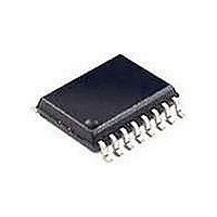
RE46C190S16F Microchip Technology, RE46C190S16F Datasheet - Page 3

RE46C190S16F
Manufacturer Part Number
RE46C190S16F
Description
MOSFET & Power Driver ICs 3V E-Cal Photo S.D. IC
Manufacturer
Microchip Technology
Type
CMOS Photoelectric Smoke Detector ASIC with Interconnect and Timer Moder
Datasheet
1.RE46C190S16F.pdf
(42 pages)
Specifications of RE46C190S16F
Product
Driver ICs - Various
Supply Voltage (max)
5 V
Supply Voltage (min)
2 V
Supply Current
1 uA
Maximum Operating Temperature
+ 60 C
Mounting Style
SMD/SMT
Minimum Operating Temperature
- 10 C
Output Current
- 4 mA
Output Voltage
8.5 V
Package / Case
SOIC-16
Input Voltage
5V
Ic Output Type
Open Drain
Sensor Case Style
SOIC
No. Of Pins
16
Supply Voltage Range
2V To 5V
Lead Free Status / RoHS Status
Lead free / RoHS Compliant
Available stocks
Company
Part Number
Manufacturer
Quantity
Price
Company:
Part Number:
RE46C190S16F
Manufacturer:
MCP
Quantity:
50
Company:
Part Number:
RE46C190S16F
Manufacturer:
MICROCHIP
Quantity:
12 000
TYPICAL BATTERY APPLICATION
2010 Microchip Technology Inc.
RED
Battery
330
Note 1: C2 should be located as close as possible to the device power pins, and C1 should be located as close
R6
D4
V
3V
GREEN
BST
2: R3, R4 and C5 are typical values and may be adjusted to maximize sound pressure.
3: DC-DC converter in High Boost mode (nominal V
4: Schottky diode D1 must have a maximum peak current rating of at least 1.5A. For best results it should
5: Inductor L1 must have a maximum peak current rating of at least 1.5A.
100
TP1
R7
D5
as possible to V
and is therefore very sensitive to series resistance. Critical components of this resistance are the
inductor DC resistance, the internal resistance of the battery and the resistance in the connections from
the inductor to the battery, from the inductor to the LX pin and from the V
function properly under full load at V
not exceed 0.3 . The internal battery resistance should be no more than 0.5 and a low ESR capacitor
of 10 µF or more should be connected in parallel with the battery, to average the current draw over the
boost converter cycle.
have forward voltage specification of less than 0.5V at 1A, and low reverse leakage.
10 µF
C1
100
TP2
R1
100 µF
C3
V
DD
1 µF
C2
SS
Push-to-Test/
Chamber
D2
.
Smoke
Hush
D3
DD
= 2V, the total of the inductor and interconnect resistances should
1
2
3
4
5
6
7
8
TEST
TEST2
IRP
IRN
RLED
V
IRED
V
SS
DD
RE46C190
BST
IRCAP
GLED
FEED
V
= 9.6V) can draw current pulses of greater than 1A,
LX
BST
HS
HB
IO
16
12
15
14
13
10
11
9
9
10 µH
L1
1.5M
R4
C6
33 µF
D1
SS
R5
1 nF
330
pin to the battery. In order to
C5
RE46C190
To other Units
200K
R3
DS22271A-page 3
V
BST
4.7 µF
C4


