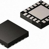
MAX2042ETP+ Maxim Integrated Products, MAX2042ETP+ Datasheet - Page 25

MAX2042ETP+
Manufacturer Part Number
MAX2042ETP+
Description
RF Mixer HI-LIN 2000-3000MHZ W/LO BUFFER
Manufacturer
Maxim Integrated Products
Datasheet
1.MAX2042ETP.pdf
(27 pages)
Specifications of MAX2042ETP+
Frequency Range
1800 MHz to 3000 MHz
Maximum Conversation Loss
7.2 dB
Maximum Operating Frequency
3000 MHz
Maximum Operating Temperature
+ 85 C
Maximum Power Dissipation
5 W
Minimum Operating Temperature
- 40 C
Mounting Style
SMD/SMT
Operating Supply Voltage
5 V
Supply Current
138 mA
Package / Case
TQFN-20
Noise Figure
7.3 dB
Rf Type
General Purpose
Supply Voltage Range
3V To 5.25V
Rf Ic Case Style
QFN
No. Of Pins
20
Operating Temperature Range
-40°C To +85°C
Peak Reflow Compatible (260 C)
Yes
Rohs Compliant
Yes
Leaded Process Compatible
Yes
Lead Free Status / RoHS Status
Lead free / RoHS Compliant
A properly designed PCB is an essential part of any
RF/microwave circuit. Keep RF signal lines as short as
possible to reduce losses, radiation, and inductance.
For the best performance, route the ground pin traces
directly to the exposed pad under the package. The PCB
exposed pad MUST be connected to the ground plane
of the PCB. It is suggested that multiple vias be used to
connect this pad to the lower-level ground planes. This
method provides a good RF/thermal conduction path for
the device. Solder the exposed pad on the bottom of the
device package to the PCB.
Table 1. Downconverter Mode Component Values
Table 2. Upconverter Mode Component Values
Upconversion/Downconversion Mixer with LO Buffer
C2, C6, C8, C11
C2, C6, C8, C11
DESIGNATION
DESIGNATION
C3, C9
C3, C9
C10
C10
C1
C5
U1
C1
C5
U1
R1
R1
T1
T1
______________________________________________________________________________________
SiGe High-Linearity, 2000MHz to 3000MHz
QTY
QTY
1
4
0
0
1
1
1
1
1
4
0
0
1
1
1
1
Layout Considerations
8.2pF microwave capacitor (0402)
0.01FF microwave capacitors (0402)
Not installed, capacitors
Not installed, capacitor
2pF microwave capacitor (0402)
698I Q1% resistor (0402)
1:1 IF balun MABAES0029
MAX2042 IC (20 TQFN)
8.2pF microwave capacitor (0402)
0.01FF microwave capacitors (0402)
Not installed, capacitors
Not installed, capacitor
2pF microwave capacitor (0402)
698I Q1% resistor (0402)
1:1 IF balun MABAES0029
MAX2042 IC (20 TQFN)
DESCRIPTION
DESCRIPTION
Proper voltage-supply bypassing is essential for high-
frequency circuit stability. Bypass each V
capacitors shown in the Typical Application Circuit and
see Tables 1 and 2.
The exposed pad (EP) of the MAX2042’s 20-pin thin QFN
package provides a low thermal-resistance path to the
die. It is important that the PCB on which the MAX2042
is mounted be designed to conduct heat from the EP. In
addition, provide the EP with a low-inductance path to
electrical ground. The EP MUST be soldered to a ground
plane on the PCB, either directly or through an array of
plated via holes.
Exposed Pad RF/Thermal Considerations
Murata Electronics North America, Inc.
Murata Electronics North America, Inc.
—
—
Murata Electronics North America, Inc.
Digi-Key Corp.
M/A-Com, Inc.
Maxim Integrated Products, Inc.
Murata Electronics North America, Inc.
Murata Electronics North America, Inc.
—
—
Murata Electronics North America, Inc.
Digi-Key Corp.
M/A-Com, Inc.
Maxim Integrated Products, Inc.
COMPONENT SUPPLIER
COMPONENT SUPPLIER
Power-Supply Bypassing
CC
pin with the
25


