NTE397 NTE ELECTRONICS, NTE397 Datasheet
NTE397
Manufacturer Part Number
NTE397
Description
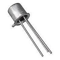
Replacement Semiconductors TO-39 PNP PWR AMP SW
Manufacturer
NTE ELECTRONICS
Datasheet
1.NTE397.pdf
(2 pages)
Specifications of NTE397
Transistor Polarity
PNP
Collector Emitter Voltage V(br)ceo
-300V
Power Dissipation Pd
10W
Dc Collector Current
-1A
Dc Current Gain Hfe
30
Operating Temperature Range
-65°C To +200°C
Lead Free Status / RoHS Status
Lead free / RoHS Compliant
Lead Free Status / RoHS Status
Lead free / RoHS Compliant, Lead free / RoHS Compliant


Absolute Maximum Ratings:
Collector–Emitter Voltage, V
Collector–Base Voltage, V
Emitter–Base Voltage, V
Continuous Collector Current, I
Base Current, I
Total Device Dissipation (T
Operating Junction Temperature Range, T
Storage Temperature Range, T
Thermal Resistance, Junction–to–Case, R
Thermal Resistance, Junction–to–Ambient, R
Electrical Characteristics: (T
Note 1. Pulse Test; Pulse Width
CAUTION: The sustaining voltage must not be measured on a curve tracer.
OFF Characteristics
Collector–Emitter Sustaining Voltage V
Collector Cutoff Current
Emitter Cutoff Current
ON Characteristics
DC Current Gain
Small–Signal Characteristics
Output Capacitance
Input Capacitance
Small–Signal Current Gain
Real Part of Input Impedance
Derate Above 25 C
Parameter
B
. . . . . . . . . . . . . . . . . . . . . . . . . . . . . . . . . . . . . . . . . . . . . . . . . . . . . . . . . . . . . . . .
Power Amplifier & High Speed Switch
EBO
CBO
C
. . . . . . . . . . . . . . . . . . . . . . . . . . . . . . . . . . . . . . . . . . . . . . . . . . . . . .
CEO
= +25 C), P
. . . . . . . . . . . . . . . . . . . . . . . . . . . . . . . . . . . . . . . . . . . . . . . . . . . . . . . . . .
stg
C
A
. . . . . . . . . . . . . . . . . . . . . . . . . . . . . . . . . . . . . . . . . . . . . . . . . . . . . .
. . . . . . . . . . . . . . . . . . . . . . . . . . . . . . . . . . . . . . . . . . . . . . . . . . . . .
= +25 C unless otherwise specified)
Silicon PNP Transistor
. . . . . . . . . . . . . . . . . . . . . . . . . . . . . . . . . . . . . . . . . . . . . . . . . . . . . .
. . . . . . . . . . . . . . . . . . . . . . . . . . . . . . . . . . . . . . . . . .
Symbol
Re(h
(Compl to NTE396)
CEO(sus)
300 s, Duty Cycle
I
I
C
C
h
CBO
EBO
h
obo
FE
ibo
fe
ie
D
)
J
thJC
. . . . . . . . . . . . . . . . . . . . . . . . . . . . . . . . . . . . . . . . . . . .
NTE397
. . . . . . . . . . . . . . . . . . . . . . . . . . . . . . . . . .
I
V
V
I
V
V
I
V
C
C
C
thJA
CB
EB
CB
CB
CE
= 50mA, I
= 50mA, V
= 10mA, V
. . . . . . . . . . . . . . . . . . . . . . . . . . . . . . . . . . . .
= 6V, I
= 280V, I
= 10V, I
= 5V, I
= 10V, I
. . . . . . . . . . . . . . . . . . . . . . . . . . . . . . . . . .
Test Conditions
C
C
B
E
C
= 0
= 0, f = 1MHz
CE
CE
2%.
E
= 0, f = 1MHz
= 0, Note 1
= 5mA, f = 1MHz
= 0
= 10V
= 10V, f = 1MHz
Min Typ Max Unit
300
30
25
–
–
–
–
–
–65 to +200 C
–65 to +200 C
–
–
–
–
–
–
–
–
120
300
50
20
15
75
57mW/ C
17.5 C/W
–
–
150 C/W
500mA
300V
350V
10W
pF
pF
V
A
A
6V
1A
Related parts for NTE397
Image
Part Number
Description
Manufacturer
Datasheet
Request
R

Part Number:
Description:
TRANSISTOR,BJT,PNP,300V V(BR)CEO,500MA I(C),TO-126
Manufacturer:
NTE ELECTRONICS
Datasheet:

Part Number:
Description:
ICS,NTE LED FLASHLIGHTS,ICS,RED TRAFFIC AND SAFETY WAND FOR LW-PRO4000-BLK. MOLDED TRANSLUCENT PLASTIC WAND,TASK LIGHTING,LIGHTWAVE? LED FLASHLIGHTS ,NTE ELECTRONICS
Manufacturer:
NTE ELECTRONICS

Part Number:
Description:
Fuse; Non-Resettable; 15A; Dims 0.16x0.457"; Axial; 120-277VAC; PCB; NTE Series
Manufacturer:
NTE Electronics, Inc.
Datasheet:
Part Number:
Description:
Fuse; Non-Resettable; 15A; Dims 0.16x0.457"; Axial; 120-277VAC; PCB; NTE Series
Manufacturer:
NTE Electronics, Inc.
Datasheet:
Part Number:
Description:
Fuse; Non-Resettable; 15A; Dims 0.16x0.457"; Axial; 120-277VAC; PCB; NTE Series
Manufacturer:
NTE Electronics, Inc.
Datasheet:
Part Number:
Description:
Fuse; Non-Resettable; 15A; Dims 0.16x0.457"; Axial; 120-277VAC; PCB; NTE Series
Manufacturer:
NTE Electronics, Inc.
Datasheet:
Part Number:
Description:
Fuse; Non-Resettable; 15A; Dims 0.16x0.457"; Axial; 120-277VAC; PCB; NTE Series
Manufacturer:
NTE Electronics, Inc.
Datasheet:
Part Number:
Description:
Fuse; Non-Resettable; 15A; Dims 0.16x0.457"; Axial; 120-277VAC; PCB; NTE Series
Manufacturer:
NTE Electronics, Inc.
Datasheet:
Part Number:
Description:
Fuse; Non-Resettable; 15A; Dims 0.16x0.457"; Axial; 120-277VAC; PCB; NTE Series
Manufacturer:
NTE Electronics, Inc.
Datasheet:
Part Number:
Description:
Fuse; Non-Resettable; 15A; Dims 0.16x0.457"; Axial; 120/250VAC; PCB; NTE Series
Manufacturer:
NTE Electronics, Inc.
Datasheet:
Part Number:
Description:
MOTOR START AC ELECTROLYTIC
Manufacturer:
NTE [NTE Electronics]
Datasheet:
Part Number:
Description:
SOLID TANTALUM
Manufacturer:
NTE [NTE Electronics]
Datasheet:
Part Number:
Description:
HIGH-FREQ ALUMINUM ELECTROLYTIC
Manufacturer:
NTE [NTE Electronics]
Datasheet:
Part Number:
Description:
SNAP-IN MOUNT ALUMINUM ELECTROLYTIC
Manufacturer:
NTE [NTE Electronics]
Datasheet:

Part Number:
Description:
Replacement Semiconductors TO-220 NPN PWR AMP
Manufacturer:
NTE ELECTRONICS
Datasheet:
NTE397 Summary of contents
Page 1
... Input Capacitance Small–Signal Current Gain Real Part of Input Impedance Note 1. Pulse Test; Pulse Width CAUTION: The sustaining voltage must not be measured on a curve tracer. NTE397 Silicon PNP Transistor (Compl to NTE396 CEO . . . . . . . . . . . . . . . . . . . . . . . . . . . . . . . . . . . . . . . . . . . . . . . . . . . . . . ...
Page 2
Max .500 (12.7) Min Emitter 45 .031 (.793) .370 (9.39) Dia Max .355 (9.03) Dia Max .018 (0.45) Base Collector/Case ...