MA1-B-34-610-1-A26-B-C Carling Technologies, MA1-B-34-610-1-A26-B-C Datasheet - Page 3
MA1-B-34-610-1-A26-B-C
Manufacturer Part Number
MA1-B-34-610-1-A26-B-C
Description
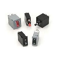
Circuit Breakers 10 A ONE POLE ANGLED
Manufacturer
Carling Technologies
Series
Mr
Datasheet
1.MB1-B-34-620-1-A27-B-C.pdf
(16 pages)
Specifications of MA1-B-34-610-1-A26-B-C
Product Type
Circuit Breakers
Current Rating
10 Amps
Voltage Rating
250 VoltsAC / 80 VoltsDC
Trip Time
1 s to 15 s
Mounting Style
Snap In
Termination Style
Quick Connect
Circuit Function
Series Trip (Current)
Color
White
Dielectric Strength
1.5 KV
Features
The exclusive Rockerguard bezel helps prevent inadvertent actuation
Height
34.93 mm
Illuminated
No
Length
35.43 mm
Product
Hydraulic Magnetic Circuit Breakers
Width
17.27 mm
Number Of Poles
1 Pole
Actuator Type
Rocker
Lead Free Status / RoHS Status
Lead free / RoHS Compliant


20
M-Series General Specifications
Electrical
Maximum Voltage
Current Ratings
Auxiliary Switch Rating
Insulation Resistance
Dielectric Strength
Resistance, Impedance
Pulse Tolerance Curves
125/250 VAC 50/60 Hz, 80 VDC
(See Rating Tables.)
Standard current coils: 0.100, 0.250,
0.500, 0.750, 1.00 thru 15.0 in 1
amp increments, 18.0,
20.0, 25.0, 30.0. Other ratings avail-
able - see Ordering Scheme.
SPDT; 7A 250VAC, 7A (Res)
28VDC, 4A (Ind.) 28VDC, 0.25A
80VDC (Res) (silver contacts), 0.1A
125VAC (gold contacts).
Minimum of 100 Megohms at 500
VDC.
UL, CSA 1500V, 50/60 Hz for one
minute between all electrically isolat-
ed terminals. M-Series Circuit
Breakers comply with the 8mm
spacing and 3750 V 50/60Hz dielec-
tric requirements from hazardous
voltage to operator accessible sur-
faces, per Publications IEC 380,
435, 950, EN 60950 and VDE 0805.
Values from Line to Load Terminal -
based on Series Trip Circuit Breaker.
Mechanical
Endurance
Trip Free
Trip Indication
Physical
Number of Poles
Internal Circuit Configurations Series with or without Auxiliary
Weight
Standard Colors
Environmental
Designed and tested in accordance with requirements of specifi-
cation MIL-PRF-55629 & MIL-STD-202 as follows:
Shock
Vibration
Moisture Resistance
Salt Spray
Thermal Shock
Operating Temperature
Chemical Resistance
10,000 ON-OFF operations @ 6 per
minute with rated Current and
Voltage.
All M-Series Circuit Breakers will trip
on overload, even when actuator is
forcibly held in the ON position.
The actuator moves positively to the
OFF position when an overload
causes the circuit breaker to trip.
1 or 2
Switch.
Switch Only with or without Auxiliary
Switch.
Approximately 30 grams/pole
(Approximately 1.07 ounces/pole)
See Ordering Scheme.
Withstands 100 Gs, 6ms, sawtooth
while carrying rated current per
Method 213, Cond. I. Instantaneous
curves tested at 80% of rated current.
Withstands 0.060" excursion from 10-
55 Hz, and 10 Gs 55-500 Hz, at rated
current per Method 204C, Test
Condition A. Instantaneous curves
tested at 80% of rated current.
Method 106D, i.e., ten 24-hour
cycles @ + 25°C to +65°C, 80-98% RH.
Method 101, Condition A (90-95%
RH @ 5% NaCl Solution, 96 hrs).
Method 107D, Condition A (Five
cycles @ -55°C to +25°C to +85°C
to +25°C).
-40° C to +85° C
Only the outside surfaces of the case
and the handles may be cleaned with
detergents or alcohol. Organic (hydro-
carbon based) solvents are not rec-
ommended because they attack plas-
tics. Caution should be taken when
solvents are used to clean and
remove flux from terminals. Lubricants
should not be introduced into the han-
dle/bushing openings.
www.carlingtech.com
Related parts for MA1-B-34-610-1-A26-B-C
Image
Part Number
Description
Manufacturer
Datasheet
Request
R

Part Number:
Description:
CIRCUIT BREAKER MAG 10A PANEL MT
Manufacturer:
Carling Technologies
Datasheet:

Part Number:
Description:
Circuit Breakers 10 A ONE POLE ANGLED
Manufacturer:
Carling Technologies
Datasheet:

Part Number:
Description:
Toggle Switches CARLING TECHNOLOGIES
Manufacturer:
Carling Technologies
Datasheet:
Part Number:
Description:
CARLING POWER SWITCH LIGHTED 10 AMP 250 VOLT AC
Manufacturer:
Carling Technologies
Part Number:
Description:
CARLING SWITCH
Manufacturer:
Carling Technologies

Part Number:
Description:
SWITCH PB SPST OFF-MOM SCRW TERM
Manufacturer:
Carling Technologies
Datasheet:
Part Number:
Description:
SWITCH
Manufacturer:
Carling Technologies
Datasheet:
Part Number:
Description:
LIGHT INDICATOR GRN 12VDC PNLMNT
Manufacturer:
Carling Technologies
Part Number:
Description:
CONTURA ILL INDICATOR 12V RED
Manufacturer:
Carling Technologies
Part Number:
Description:
Current Regulator Diodes CURRENT REGULATOR DIODES 3.6mA
Manufacturer:
Carling Technologies
Part Number:
Description:
Rocker Switches
Manufacturer:
Carling Technologies
Datasheet: