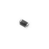
ERT-J1VR103J Panasonic, ERT-J1VR103J Datasheet - Page 7

ERT-J1VR103J
Manufacturer Part Number
ERT-J1VR103J
Description
Thermistors - NTC 10K OHM 5%
Manufacturer
Panasonic
Series
ERTr
Type
NTCr
Specifications of ERT-J1VR103J
Resistance
10 KOhms
Tolerance
5 %
Termination Style
SMD/SMT
Operating Temperature Range
- 30 C to + 125 C
Dimensions
0.80 mm W x 1.60 mm L x 0.8 mm H
Power Rating
0.4 W
Temperature Coefficient
4250 k PPM / C
Package / Case
0603
Lead Free Status / RoHS Status
Lead free / RoHS Compliant
Available stocks
Company
Part Number
Manufacturer
Quantity
Price
Part Number:
ERT-J1VR103J
Manufacturer:
PANASONIC/松下
Quantity:
20 000
4 Soldering Flux and Solder
5 Soldering
Fig.6 Recommended Soldering Temperature-Time
5-1 Flow Soldering
(1) Soldering Flux:
l
l
(2) Water soluble type Soldering Flux:
In flow soldering process, abnormal and large
thermal and mechanical stresses, caused by
a ÒTemperature GradientÓ between the
mounted Thermistors and melted solder in a
soldering bath can result in failure and/or damage
to the Thermistors. Therefore it is essential that the
soldering process shall be controlled by the
following recommended conditions and
precautions. (See Fig.6)
(1) Application of Flux:
(2) Preheating:
(3) Immersion to Soldering Bath:
(4) Cooling:
(5) Flux Cleaning:
The content of halogen in the soldering flux
should be 0.2 wt% or less.
Rosin-based and non-activated soldering flux is
recommended.
In case of water soluble type soldering flux
being applied, the flux residue on the surface of
PC boards may have influences on the
reliability of the components and be the
cause of deterioration and possible failures.
Profile (Flow soldering)
Soldering flux shall be applied to
the mounted Thermistors thinly and uniformly
using the forming method.
The mounted Thermistors/Components shall be
preheated sufficiently so that the ÒTemperature
GradientÓ between the Thermistors/components
and the melted solder shall be 150 ¡C or below.
The Thermistors should be immersed into a soldering
bath of 240 to 260 ¡C for 3 to 5 seconds.
The Thermistors shall be cooled gradually to
room ambient temperature after soldering.
When the Thermistors are immersed into
cleaning solvent, it shall be confirmed that the
surface temperature of devices do not exceed
100 ¡C.
Fig.7 Recommended Soldering Temperature-Time Profile
5-2 Reflow Soldering
In reflow soldering process, the mounted Ther-
mistors / components are generally heated and sol-
dered by a thermal conduction system such as an
ÒInfrared radiation and hot blast soldering systemÓ
or a ÒVapor Phase Soldering System (VPS)Ó, Large
temperature gradients such as a rapid heating and
cooling in the process may cause electrical failures
and mechanical damage to the device. It is es-
sential that the soldering process adhere to the
following recommended conditions and
precautions. (See Fig.7)
(1) Preheating: 140 to 160 ¡C
(2) Temperature increasing stage: 2 to 5 ¡C / s
(3) Main heating stage: 220 ¡C min. within 20s
(4) Cooling:
(5) Flux Cleaning:
Notes: If the mounted Thermistors / components
(Reflow Soldering)
After the soldering, the mounted Thermistors / com-
ponents shall be gradually cooled to room
ambient temperature to prevent mechanical
damages such as cracking of the device.
When the mounted Thermistors / components are im-
mersed into cleaning solvent, it shall be
comfirmed that the surface temperature of
devices do not exceed 100 ¡C.
are partially heated in the soldering pro-
cess, the device may be separated from
the printed circuit board by the surface
tension of partially melted solder, and
stand up like a ÒTombstoneÓ
NTC Thermistors (Chip Type)


