A5839-U1 Antenova, A5839-U1 Datasheet - Page 6
A5839-U1
Manufacturer Part Number
A5839-U1
Description
Antennas Reference Board for Rufa 2.4 GHz Left
Manufacturer
Antenova
Datasheet
1.A5887-U1.pdf
(14 pages)
Specifications of A5839-U1
Dimensions
50.1 mm L x 21 mm W
Frequency Range
2.4 GHz to 2.5 GHz
Vswr
1.8:1
Technology Type
Reference Board for Internal SMD Chip Antenna
Frequency
2.4 GHz
Gain
2.1 dBi
Termination Style
SMA
Lead Free Status / RoHS Status
Lead free / RoHS Compliant


10 Electrical interface
10-1 Transmission lines
10-2 Matching circuit
Integrated Antenna and RF Solutions
•
•
•
Once the material for the PCB has been chosen (PCB thickness and dielectric constant), a
coplanar transmission line can easily be designed using any of the commercial software
packages for transmission line design. For the chosen PCB thickness, copper thickness and
substrate dielectric constant, the program will calculate the appropriate transmission line width
and gaps on either side of the track so the characteristic impedance of the coplanar
transmission line is 50 Ω.
The antenna requires a matching circuit that must be optimized for each customer’s product.
The matching circuit will require up to three components and the following pad layout should be
designed into the device so the correct circuit can be installed:
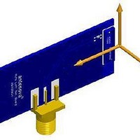
The antenna feed pad and the antenna ground pad are indicated in the drawing above.
Additional pads are for mechanical attachment only and should not be grounded.
All transmission lines should be designed to have a characteristic impedance of 50 Ω
The length of the transmission lines should be kept to a minimum
Any other parts of the RF system like transceivers, power amplifiers, etc, should also be
designed to have an impedance of 50 Ω
Rufa 2.4 GHz SMD Antenna
Part No. A5839 / A5887
Product Specification AE020157-N
6
Related parts for A5839-U1
Image
Part Number
Description
Manufacturer
Datasheet
Request
R

Part Number:
Description:
ANTENNA CHIP 2.4GHZ SMD LEFT FD
Manufacturer:
Antenova
Datasheet:

Part Number:
Description:
ANTENNA CHIP 2.4GHZ SMD
Manufacturer:
Antenova
Datasheet:

Part Number:
Description:
ANTENNA FUSCA 2.4GHZ SMD
Manufacturer:
Antenova
Datasheet:

Part Number:
Description:
ANTENNA CHIP 2.4GHZ SMD RIGHT FD
Manufacturer:
Antenova
Datasheet:

Part Number:
Description:
ANTENNA MIXTUS 2.4/5GHZ SMD
Manufacturer:
Antenova
Datasheet:

Part Number:
Description:
ANTENNA CHIP 2.4GHZ SMD
Manufacturer:
Antenova
Datasheet:

Part Number:
Description:
ANTENNA BREVIS GPS 1575MHZ SMD
Manufacturer:
Antenova
Datasheet:

Part Number:
Description:
ANTENNA CALVUS 824-960MHZ SMD
Manufacturer:
Antenova
Datasheet:

Part Number:
Description:
ANTENNA GPS 1575MHZ SMD
Manufacturer:
Antenova
Datasheet:

Part Number:
Description:
ANTENNA 2.4GHZ SNAP-IN 0.8MM PCB
Manufacturer:
Antenova
Datasheet:

Part Number:
Description:
ANTENNA 2.4GHZ W/SMA
Manufacturer:
Antenova
Datasheet:

Part Number:
Description:
ANTENNA CHIP 2.4GHZ SMD LEFT FD
Manufacturer:
Antenova
Datasheet:

Part Number:
Description:
ANTENNA CHIP 2.4GHZ SMD RIGHT FD
Manufacturer:
Antenova
Datasheet:

Part Number:
Description:
ANTENNA REFLEXUS 824-960MHZ SMD
Manufacturer:
Antenova
Datasheet:
Part Number:
Description:
ANTENNA CHIP 2.4GHZ SMD
Manufacturer:
Antenova
Datasheet: