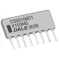
20110D1X104K5P Vishay, 20110D1X104K5P Datasheet - Page 2

20110D1X104K5P
Manufacturer Part Number
20110D1X104K5P
Description
Capacitor Arrays & Networks Cap Net .1uF 10%
Manufacturer
Vishay
Series
201r
Datasheet
1.20108D1X104K5P.pdf
(3 pages)
Specifications of 20110D1X104K5P
Voltage Rating
50 Volts
Operating Temperature Range
- 55 C to + 125 C
Termination Style
SIP
Dimensions
25.40 mm L
Dissipation Factor Df
+/- 2.5
Lead Spacing
2.54 mm
Product
Ceramic Capacitor Networks
Capacitance
0.1 uF
Tolerance
10 %
Temperature Coefficient
X7R
Package / Case
CS201
Capacitance Tolerance
± 10%
Capacitor Mounting
Through Hole
Capacitor Terminals
Radial Leaded
Peak Reflow Compatible (260 C)
No
Rohs Compliant
No
Capacitor Dielectric Type
Ceramic
Lead Free Status / RoHS Status
Lead free / RoHS Compliant
Other names
CS20110D1X104K5
DIMENSIONS
Pin #1 is extreme left-hand terminal on side with marking.
Document Number: 31522
Revision: 14-Jan-10
1
NUMBER
OF PINS
4 pin
5 pin
6 pin
7 pin
8 pin
SCHEMATICS
Common Bus - 1 Ground Lead
2
Schematic 1
3
4
5
(0.508)
in inches (millimeters)
0.020
0.100 ± 0.005 (2.54 ± 0.127)
6
at Point of Egress
Non-Cumulative
n-1
0.400 (10.16)
0.500 (12.70)
0.600 (15.24)
0.700 (17.78)
0.800 (20.32)
MAXIMUM
n
L
Thick Film Capacitor Networks, Single-In-Line,
For technical questions, contact:
Max.
L
1
2
Conformal Coated SIP
NUMBER
OF PINS
10 pin
11 pin
12 pin
13 pin
9 pin
3
Isolated Capacitor Sections
0.050 (1.27)
Schematic 3
4
5
0.300
(7.62)
6
ff2aresistors@vishay.com
0.900 (22.86)
1.000 (25.40)
1.100 (27.94)
1.200 (30.48)
1.300 (33.02)
0.050 (1.27)
MAXIMUM
7
Ty p.
L
(0.254)
0.010
8
(3.43 + 0.381 - 0.254)
0.135 + 0.015 - 0.010
n-1
0.085 (2.160)
n
T yp.
Seating Plan e
for 0.040 (1.016) Ø Hole
0.135 (3.43)
NUMBER
OF PINS
0
14 pin
15 pin
16 pin
17 pin
18 pin
Max.
.
007 (0.178) Ref.
Common Bus - 2 Ground Leads
1
2
Schematic 4
3
1.400 (35.56)
1.500 (38.10)
1.600 (40.64)
1.700 (43.18)
1.800 (45.72)
4
Vishay Dale
MAXIMUM
www.vishay.com
CS201
L
n-1
n
2


