DEBF33A103ZA2B Murata, DEBF33A103ZA2B Datasheet - Page 28
DEBF33A103ZA2B
Manufacturer Part Number
DEBF33A103ZA2B
Description
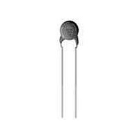
Ceramic Disc Capacitors 0.01uF 1000volts F +80-20%
Manufacturer
Murata
Series
DEBr
Type
Ceramic Discr
Datasheet
1.DEBF33A103ZA2B.pdf
(72 pages)
Specifications of DEBF33A103ZA2B
Voltage Rating
1 KVolts
Operating Temperature Range
- 25 C to + 85 C
Termination Style
Radial
Product
High Voltage Ceramic Disc Capacitors
Dimensions
10 mm Dia.
Capacitance
0.01 uF
Tolerance
20 %
Temperature Coefficient
F
Lead Spacing
5 mm
Capacitance Tolerance
+80, -20%
Capacitor Case Style
Radial Leaded
No. Of Pins
2
Capacitor Mounting
Through Hole
Rohs Compliant
Yes
Tolerance (+ Or -)
-20% to 80%
Voltage
1000VDC
Temp Coeff (dielectric)
F
Operating Temp Range
-25C to 85C
Mounting Style
Through Hole
Package / Case
Not Required
Construction
Radial
Lead Spacing (nom)
5mm
Product Length (mm)
Not Requiredmm
Product Depth (mm)
4mm
Product Height (mm)
Not Requiredmm
Product Diameter (mm)
10mm
Lead Diameter (nom)
0.6mm
Seated Plane Height
13mm
Lead Free Status / RoHS Status
Lead free / RoHS Compliant
Available stocks
Company
Part Number
Manufacturer
Quantity
Price
Company:

Part Number:
DEBF33A103ZA2B
Manufacturer:
MURATA
Quantity:
37 584


5
!Note
• This PDF catalog is downloaded from the website of Murata Manufacturing co., ltd. Therefore, it’s specifications are subject to change or our products in it may be discontinued without advance notice. Please check with our
• This PDF catalog has only typical specifications because there is no space for detailed specifications. Therefore, please approve our product specifications or transact the approval sheet for product specifications before ordering.
sales representatives or product engineers before ordering.
!Note
4. Fail-Safe
FAILURE TO FOLLOW THE ABOVE CAUTIONS MAY
RESULT, WORST CASE, IN A SHORT CIRCUIT
AND CAUSE FUMING OR PARTIAL DISPERSION
WHEN THE PRODUCT IS USED.
26
(2) Voltage Applied Method
Safety Recognized Ceramic Capacitors !Caution
When the withstanding voltage is applied, capacitor's
lead or terminal should be firmly connected to the output
of the withstanding voltage test equipment, and then the
voltage should be raised from near zero to the test
voltage.
If the test voltage without the raise from near zero voltage
would be applied directly to capacitor, test voltage should
be applied with the zero cross*. At the end of the test
time, the test voltage should be reduced to near zero,
and then capacitor's lead or terminal should be taken off
the output of the withstanding voltage test equipment.
If the test voltage without the raise from near zero voltage
would be applied directly to capacitor, the surge voltage
may arise, and therefore, a defect may be caused.
*ZERO CROSS is the point where voltage sine wave
When capacitor is broken, failure may result in a short
circuit. Be sure to provide an appropriate fail-safe
function like a fuse on your product if failure could result
in an electric shock, fire or fuming.
Continued from the preceding page.
passes 0V. See figure at right.
• Please read rating and !CAUTION (for storage, operating, rating, soldering, mounting and handling) in this catalog to prevent smoking and/or burning, etc.
• This catalog has only typical specifications because there is no space for detailed specifications. Therefore, please approve our product specifications or transact the approval sheet for product specifications before ordering.
0V
Voltage sine wave
zero cross
C85E.pdf
08.10.29
Related parts for DEBF33A103ZA2B
Image
Part Number
Description
Manufacturer
Datasheet
Request
R

Part Number:
Description:
Murata Microblower 20x20 DCDC Driver Board - Samples Only
Manufacturer:
Murata
Part Number:
Description:
357-036-542-201 CARDEDGE 36POS DL .156 BLK LOPRO
Manufacturer:
Murata
Datasheet:
Part Number:
Description:
Manufacturer:
Murata
Datasheet:
Part Number:
Description:
Manufacturer:
Murata
Datasheet:
Part Number:
Description:
Manufacturer:
Murata
Datasheet:
Part Number:
Description:
Manufacturer:
Murata
Datasheet:
Part Number:
Description:
Manufacturer:
Murata
Datasheet:
Part Number:
Description:
Manufacturer:
Murata
Datasheet:
Part Number:
Description:
Manufacturer:
Murata
Datasheet:
Part Number:
Description:
BLM21BD751SN1On-Board Type (DC) EMI Suppression Filters
Manufacturer:
Murata
Datasheet:
Part Number:
Description:
BLM15AG100SN1On-Board Type (DC) EMI Suppression Filters
Manufacturer:
Murata
Datasheet:
Part Number:
Description:
NFE31PT222Z1E9On-Board Type (DC) EMI Suppression Filters
Manufacturer:
Murata
Datasheet:
Part Number:
Description:
Chip Coil
Manufacturer:
Murata
Datasheet:
Part Number:
Description:
Chip Coil
Manufacturer:
Murata
Datasheet: