GRM219R72A102KA01D Murata, GRM219R72A102KA01D Datasheet
GRM219R72A102KA01D
Manufacturer Part Number
GRM219R72A102KA01D
Description
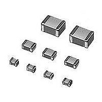
Multilayer Ceramic Capacitors (MLCC) - SMD/SMT 0805 1000pF 100volts X7R 10%
Manufacturer
Murata
Series
GRMr
Datasheet
1.GRM216R71H183KA01D.pdf
(5 pages)
Specifications of GRM219R72A102KA01D
Voltage Rating
100 Volts
Operating Temperature Range
- 55 C to + 125 C
Temperature Coefficient / Code
X7R
Product
General Type MLCCs
Dimensions
1.25 mm W x 2 mm L x 0.85 mm H
Termination Style
SMD/SMT
Capacitance
1000 pF
Tolerance
10 %
Package / Case
0805 (2012 metric)
Lead Free Status / RoHS Status
Lead free / RoHS Compliant
Available stocks
Company
Part Number
Manufacturer
Quantity
Price
Company:

Part Number:
GRM219R72A102KA01D
Manufacturer:
MURATA
Quantity:
600 000


No.
1
2
3
4
5
6
7
8
Operating
Temperature
Range
Rated Voltage
Appearance
Dimensions
Dielectric Strength
Insulation
Resistance
Capacitance
Q/
Dissipation Factor
(D.F.)
Item
Y55 to W125D
See the previous pages
No defects or abnormalities
Within the specified dimensions
No defects or abnormalities
C V 0.047 µ F : More than 10,000MΩ
C G 0.047 µ F : 500Ω · F
Within the specified tolerance
30pF and over : QU1000
30pF and below :
C : Nominal Capacitance (pF)
Compensating Type
Temperature
Q U400W20C
Specifications
B1, B3, F1, R6 : Y25 to W85D
R1, R7 : Y55 to W125D
E4 : W10 to W85D
F5 : Y30 to W85D
[B1, B3, R1, R6, R7, E4, C8]
W.V. : 25V min. : 0.025 max.
W.V. : 16/10V : 0.035 max.
W.V. : 6.3/4V
[F1, F5]
W.V. : 25V min.
W.V. : 16/10V : 0.125 max.
W.V. : 6.3V : 0.15 max.
High Dielectric Type
C : Nominal Capacitance
: 0.05 max. (CF0.1µF)
: 0.09 max. (CU0.1µF)
: 0.05 max. (CF3.3µF)
: 0.1 max. (CU3.3µF)
Reference temperature : 25D
(2 , 3 , 4 , B1, B3, F1, R1, R6 : 20D)
The rated voltage is defined as the maximum voltage which
may be applied continuously to the capacitor.
When AC voltage is superimposed on DC voltage, V
whichever is larger, should be maintained within the rated
voltage range.
Visual inspection
Using calipers
No failure should be observed when *300% of the rated voltage
(temperature compensating type) or 250% of the rated voltage
(high dielectric constant type) is applied between the
terminations for 1 to 5 seconds, provided the charge/discharge
current is less than 50mA.
The insulation resistance should be measured with a DC
voltage not exceeding the rated voltage at 20/25D and 75%RH
max. and within 2 minutes of charging, provided the charge/
discharge current is less than 50mA.
The capacitance/Q/D.F. should be measured at 20/25D at the
frequency and voltage shown in the table.
Frequency
Item
Voltage
Char.
∆C to ∆U, 1X
(1000pF and
0.5 to 5Vrms
1T0.1MHz
below)
Test Method
*200% for 500V
Continued on the following page.
∆C to ∆U, 1X
1T0.2Vrms
(more than
R6, R7, F5
B1, B3, F1
1T0.1kHz
1000pF)
0.5T0.05Vrms
1T0.1kHz
P-P
E4
or V
O-P
,
Related parts for GRM219R72A102KA01D
Image
Part Number
Description
Manufacturer
Datasheet
Request
R

Part Number:
Description:
Murata Microblower 20x20 DCDC Driver Board - Samples Only
Manufacturer:
Murata
Part Number:
Description:
357-036-542-201 CARDEDGE 36POS DL .156 BLK LOPRO
Manufacturer:
Murata
Datasheet:
Part Number:
Description:
Manufacturer:
Murata
Datasheet:
Part Number:
Description:
Manufacturer:
Murata
Datasheet:
Part Number:
Description:
Manufacturer:
Murata
Datasheet:
Part Number:
Description:
Manufacturer:
Murata
Datasheet:
Part Number:
Description:
Manufacturer:
Murata
Datasheet:
Part Number:
Description:
Manufacturer:
Murata
Datasheet:
Part Number:
Description:
Manufacturer:
Murata
Datasheet:
Part Number:
Description:
BLM21BD751SN1On-Board Type (DC) EMI Suppression Filters
Manufacturer:
Murata
Datasheet:
Part Number:
Description:
BLM15AG100SN1On-Board Type (DC) EMI Suppression Filters
Manufacturer:
Murata
Datasheet:
Part Number:
Description:
NFE31PT222Z1E9On-Board Type (DC) EMI Suppression Filters
Manufacturer:
Murata
Datasheet:
Part Number:
Description:
Chip Coil
Manufacturer:
Murata
Datasheet:
Part Number:
Description:
Chip Coil
Manufacturer:
Murata
Datasheet: