TZ03Z500F169B00 Murata, TZ03Z500F169B00 Datasheet - Page 28
TZ03Z500F169B00
Manufacturer Part Number
TZ03Z500F169B00
Description
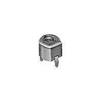
Trimmer / Variable Capacitors 6-50pF NP0+/-300ppm 50VDC 6Dx4.8H Orange
Manufacturer
Murata
Series
TZ03r
Datasheet
1.TZ03Z500F169B00.pdf
(44 pages)
Specifications of TZ03Z500F169B00
Tolerance
0.5 %
Voltage Rating
50 Volts
Operating Temperature Range
- 25 C to + 85 C
Termination Style
Radial
Product
Trimmer Capacitors - Ceramic Dielectric
Dimensions
0.16 in W x 0.24 in L x 0.19 in H
Lead Spacing
0.24 in
Capacitance Range
50 pF
Adjustment Type
Top
Capacitance Tolerance
0% To +100%
Capacitor Case Style
Radial
Capacitor Mounting
Snap-In
Rohs Compliant
Yes
Capacitor Terminals
Radial Leaded
Lead Free Status / RoHS Status
Lead free / RoHS Compliant
Available stocks
Company
Part Number
Manufacturer
Quantity
Price
Company:

Part Number:
TZ03Z500F169B00
Manufacturer:
MURATA
Quantity:
12 000
Company:
Part Number:
TZ03Z500F169B00
Manufacturer:
MURATA
Quantity:
4 000


6
!Note
• This PDF catalog is downloaded from the website of Murata Manufacturing co., ltd. Therefore, it’s specifications are subject to change or our products in it may be discontinued without advance notice. Please check with our
• This PDF catalog has only typical specifications because there is no space for detailed specifications. Therefore, please approve our product specifications or transact the approval sheet for product specifications before ordering.
sales representatives or product engineers before ordering.
!Note
1. Do not use the trimmer capacitor under atmosphere
2. Before using trimmer capacitor, please store under
3. Do not store in or near corrosive gasses.
4. Use within 6 months of delivery.
5. Do not store under direct sunlight.
1. Soldering
1. Use suitable screwdrivers that fit comfortably in
2. When adjusting with a screwdriver, do not apply
Before using trimmer capacitor, please test after
assembly in your particular mass production system.
26
(1) TZW4 series can be soldered by reflow soldering
(2) Soldering condition
(3) The amount of solder is critical.
(4) The thickness of solder paste should be printed
(5) When using soldering iron, the diameter of the
-Recommended screwdriver for manual adjustment
Notice (Storage and Operating Condition)
of RTV silicone rubber (Room Temperature
Vulcanizing Silicone Rubber) except Acetone
liberating silicone sealant.
the condition of -10 to +40 degrees C and 30
to 85%RH.
Notice (Soldering and Mounting)
Notice (Handling)
driver slot.
excessive force (preferably 1.0 N [Ref: 100gf] max.)
to minimize capacitance drift. If excessive force
applied to the screwdriver slot, it may cause
deformation of the products.
Notice (Other)
method and soldering iron. Do not use flow
soldering method (dipping).
Refer to the temperature profile.
If the soldering conditions are not suitable, e.g.,
excessive time and/or excessive temperature, the
trimmer capacitor may deviate from the specified
characteristics.
from 150 micro m to 200 micro m and the dimension
of land pattern should be Murata's standard land
pattern used at reflow soldering.
Insufficient amounts of solder can lead to
insufficient soldering strength on PCB.
Excessive amounts of solder may cause bridging
between the terminals or contact failure due to
flux wicking up.
string solder should be less than 0.5mm. The
string solder should be applied to the lower
part of the terminal only. Do not apply flux
except to the terminals. Excessive amounts of
solder and/or applying solder to the upper part
• Please read rating and !CAUTION (for storage, operating, rating, soldering, mounting and handling) in this catalog to prevent smoking and/or burning, etc.
• This catalog has only typical specifications because there is no space for detailed specifications. Therefore, please approve our product specifications or transact the approval sheet for product specifications before ordering.
VESSEL: No.9000 -1.3x30
(Murata: KMDR130)
6. Do not use the trimmer capacitor under the
2. Mounting
3. Do not apply adhesive, lock paints, or any other
3. Cleaning
(1) Corrosive gasses atmosphere
(2) In liquid (Ex. water, oil, medical liquid,
(3) Dusty/dirty atmosphere
(4) Direct sunlight
(5) Static voltage nor electric/magnetic fields
(6) Direct sea breeze
(7) Other variations of the above
(6) Our recommended chlorine content of solder is
(7) Do not use water-soluble flux (for water
(1) Do not apply excessive force (preferably 5.0 N
(2) Do not warp and/or bend PCB to prevent trimmer
(3) Use the suitable dimension of the pick-up nozzle
conditions listed below.
substances to the trimmer capacitor to secure the
rotor position. They may cause corrosion or
electrical contact problems.
Cannot be cleaned because of open construction.
(a) Solder paste: 0.2wt% max.
(b) String solder: 0.5wt% max.
(Ex. Chlorine gas, Hydrogen sulfide gas,
Ammonia gas, Sulfuric acid gas, Nitric oxie gas,
etc.)
organic solvent, etc.)
of the terminal may cause fixed metal rotor or
the contact failure due to flux invasion into
the movable part and/or the contact point. The
soldering iron should not come in contact with
the monolithic stator of the trimmer capacitor.
If such contact does occur, the trimmer
capacitor may be damaged.
as follows.
cleaning). To prevent the deterioration of
trimmer capacitor characteristics, apply flux
only to terminals.
[Ref: 500gf] max.), when the trimmer capacitor
is mounted on the PCB.
capacitor from breaking.
(1.8mm external diameter and 1.1mm bore
diameter).
T13E.pdf
08.8.27
Related parts for TZ03Z500F169B00
Image
Part Number
Description
Manufacturer
Datasheet
Request
R

Part Number:
Description:
Murata Microblower 20x20 DCDC Driver Board - Samples Only
Manufacturer:
Murata
Part Number:
Description:
357-036-542-201 CARDEDGE 36POS DL .156 BLK LOPRO
Manufacturer:
Murata
Datasheet:
Part Number:
Description:
Manufacturer:
Murata
Datasheet:
Part Number:
Description:
Manufacturer:
Murata
Datasheet:
Part Number:
Description:
Manufacturer:
Murata
Datasheet:
Part Number:
Description:
Manufacturer:
Murata
Datasheet:
Part Number:
Description:
Manufacturer:
Murata
Datasheet:
Part Number:
Description:
Manufacturer:
Murata
Datasheet:
Part Number:
Description:
Manufacturer:
Murata
Datasheet:
Part Number:
Description:
BLM21BD751SN1On-Board Type (DC) EMI Suppression Filters
Manufacturer:
Murata
Datasheet:
Part Number:
Description:
BLM15AG100SN1On-Board Type (DC) EMI Suppression Filters
Manufacturer:
Murata
Datasheet:
Part Number:
Description:
NFE31PT222Z1E9On-Board Type (DC) EMI Suppression Filters
Manufacturer:
Murata
Datasheet:
Part Number:
Description:
Chip Coil
Manufacturer:
Murata
Datasheet:
Part Number:
Description:
Chip Coil
Manufacturer:
Murata
Datasheet: