BLM18HG601SN1D Murata, BLM18HG601SN1D Datasheet - Page 140
BLM18HG601SN1D
Manufacturer Part Number
BLM18HG601SN1D
Description
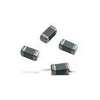
EMI/RFI Suppressors & Ferrites 0603 600 OHM
Manufacturer
Murata
Specifications of BLM18HG601SN1D
Shielding
Unshielded
Test Frequency
100 MHz
Product
Chip Ferrite Beads
Impedance
600 Ohms
Tolerance
25 %
Maximum Dc Current
200 mAmps
Maximum Dc Resistance
1 Ohms
Operating Temperature Range
- 55 C to + 125 C
Package / Case
0603 (1608 metric)
Termination Style
SMD/SMT
Dc Resistance Max
1ohm
Dc Current Rating
200mA
Ferrite Mounting
SMD
Ferrite Case Style
0603
Inductor Case Style
0603
No. Of Pins
2
Core Material
Ferrite
Resistance
1ohm
Rohs Compliant
Yes
Operating Temperature Min
-55°C
Operating Temperature Max
+125°C
Lead Free Status / RoHS Status
Lead free / RoHS Compliant
Available stocks
Company
Part Number
Manufacturer
Quantity
Price
Company:

Part Number:
BLM18HG601SN1D
Manufacturer:
Murata Electronics North Ameri
Quantity:
63 770
Company:
Part Number:
BLM18HG601SN1D
Manufacturer:
MURATA
Quantity:
25 385
Part Number:
BLM18HG601SN1D
Manufacturer:
MURATA/村田
Quantity:
20 000


!Note
138
Chip EMIFILr
<Operating Environment>
Do not use products in a chemical atmosphere such as
chlorine gas, acid or sulfide gas.
Do not use products in the environment close to the
organic solvent.
<Storage and Handling Requirements>
1. Storage Period
2. Storage Conditions
1. Cleaning
2. Soldering
3. Other
Do not use products beyond the rated current and rated
voltage as this may create excessive heat and
deteriorate the insulation resistance.
(1) Storage temperature: -10 to +40˚C
(2) Do not store products in a chemical atmosphere
• Please read rating and !CAUTION (for storage, operating, rating, soldering, mounting and handling) in this catalog to prevent smoking and/or burning, etc.
• This catalog has only typical specifications because there is no space for detailed specifications. Therefore, please review our product specifications or consult the approval sheet for product specifications before ordering.
Storage and Operating Conditions
NFM55P series should be used within 6 months, the
other series should be used within 12 months.
Solderability should be checked if this period is
exceeded.
Notice (Soldering and Mounting)
Failure and degradation of a product are caused by
the cleaning method. When you clean in conditions
that are not in mounting information, please contact
Murata engineering.
Reliability decreases with improper soldering methods.
Please solder by the standard soldering conditions
shown in mounting information.
Noise suppression levels resulting from Murata's EMI
suppression filters EMIFILr may vary, depending on
the circuits and ICs used, type of noise, mounting
pattern, mounting location, and other operating
conditions. Be sure to check and confirm in advance
the noise suppression effect of each filter, in actual
circuits, etc. before applying the filter in a commercial-
purpose equipment design.
Rating
Relative humidity: 15 to 85%
Avoid sudden changes in temperature and humidity.
such as chlorine gas, acid or sulfide gas.
!Caution/Notice
!Caution
Notice
1. Resin Coating
2. Caution for Use (NFW Series)
3. Handling of a Substrate
• Self-heating
Bending
Please provide special attention when mounting chip
EMIFILr NFM_P series in close proximity to other
products that radiate heat.
The heat generated by other products may deteriorate
the insulation resistance and cause excessive heat in
this component.
Handling
Using resin for coating/molding products may affect
the products performance.
So please pay careful attention in selecting resin.
Prior to use, please make the reliability evaluation with
the product mounted in your application set.
When you hold products with a tweezer, please hold
by the sides. Sharp materials, such as a pair of
tweezers or other material such as bristles of cleaning
brush, should not touch the winding portion of this
product to prevent breaking the wire. Mechanical
shock should not be applied to the products mounted
on the board to prevent breaking the core.
After mounting products on a substrate, do not apply
any stress to the product caused by bending or
twisting to the substrate when cropping the substrate,
inserting and removing a connector from the substrate
or tightening screw to the substrate.
Excessive mechanical stress may cause cracking in
the Product.
Soldering and Mounting
Twisting
Mar.28,2011
C31E.pdf
Related parts for BLM18HG601SN1D
Image
Part Number
Description
Manufacturer
Datasheet
Request
R

Part Number:
Description:
Murata Microblower 20x20 DCDC Driver Board - Samples Only
Manufacturer:
Murata
Part Number:
Description:
357-036-542-201 CARDEDGE 36POS DL .156 BLK LOPRO
Manufacturer:
Murata
Datasheet:
Part Number:
Description:
Manufacturer:
Murata
Datasheet:
Part Number:
Description:
Manufacturer:
Murata
Datasheet:
Part Number:
Description:
Manufacturer:
Murata
Datasheet:
Part Number:
Description:
Manufacturer:
Murata
Datasheet:
Part Number:
Description:
Manufacturer:
Murata
Datasheet:
Part Number:
Description:
Manufacturer:
Murata
Datasheet:
Part Number:
Description:
Manufacturer:
Murata
Datasheet:
Part Number:
Description:
BLM21BD751SN1On-Board Type (DC) EMI Suppression Filters
Manufacturer:
Murata
Datasheet:
Part Number:
Description:
BLM15AG100SN1On-Board Type (DC) EMI Suppression Filters
Manufacturer:
Murata
Datasheet:
Part Number:
Description:
NFE31PT222Z1E9On-Board Type (DC) EMI Suppression Filters
Manufacturer:
Murata
Datasheet:
Part Number:
Description:
Chip Coil
Manufacturer:
Murata
Datasheet:
Part Number:
Description:
Chip Coil
Manufacturer:
Murata
Datasheet: