BLM21BD272SH1L Murata, BLM21BD272SH1L Datasheet - Page 74
BLM21BD272SH1L
Manufacturer Part Number
BLM21BD272SH1L
Description
EMI/RFI Suppressors & Ferrites 0805 2.7Kohms HiSpd Signal Line Tape
Manufacturer
Murata
Series
BLM Br
Datasheet
1.BLM18AG471SH1D.pdf
(93 pages)
Specifications of BLM21BD272SH1L
Shielding
Unshielded
Test Frequency
100 MHz
Product
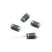
Chip Ferrite Beads
Impedance
2.7 KOhms
Tolerance
25 %
Maximum Dc Current
200 mAmps
Maximum Dc Resistance
0.8 Ohms
Operating Temperature Range
- 55 C to + 125 C
Package / Case
0805 (2012 metric)
Termination Style
SMD/SMT
Dc Resistance Max
0.8ohm
Dc Current Rating
200mA
Ferrite Mounting
SMD
Ferrite Case Style
0805 / 2012
Operating Temperature Max
+125°C
Operating Temperature Min
-55°C
Rohs Compliant
Yes
Lead Free Status / RoHS Status
Lead free / RoHS Compliant
Available stocks
Company
Part Number
Manufacturer
Quantity
Price
Company:

Part Number:
BLM21BD272SH1L
Manufacturer:
MURATA
Quantity:
240 000


4
!Note
• This PDF catalog is downloaded from the website of Murata Manufacturing co., ltd. Therefore, it’s specifications are subject to change or our products in it may be discontinued without advance notice. Please check with our
• This PDF catalog has only typical specifications because there is no space for detailed specifications. Therefore, please approve our product specifications or transact the approval sheet for product specifications before ordering.
sales representatives or product engineers before ordering.
!Note
1. Standard Land Pattern Dimensions
2. Solder Paste Printing and Adhesive Application
3. Standard Soldering Conditions
(1) Soldering Methods
Solder: Use Sn-3.0Ag-0.5Cu solder.
Flux:
o Use Rosin-based flux.
o Do not use strong acidic flux (with chlorine content
o Do not use water-soluble flux.
For additional mounting methods, please contact Murata.
72
Block Type EMIFILr SMD Type (Soldering and Mounting)
BNX024H
BNX025H
BNX024H
BNX025H
BNX024H/025H is only for reflow soldering.
exceeding 0.20wt%)
• Please read rating and !CAUTION (for storage, operating, rating, soldering, mounting and handling) in this catalog to prevent smoking and/or burning, etc.
• This catalog has only typical specifications because there is no space for detailed specifications. Therefore, please approve our product specifications or transact the approval sheet for product specifications before ordering.
Series
oUse Sn-3.0Ag-0.5Cu pattern printing solder.
oCoat with solder paste to the following thickness:
150-200 m
12.5
10.2
9.9
9.6
7.1
6.2
5.3
2.8
2.3
0
12.5
10.2
9.6
7.1
5.3
2.8
2.3
0
PSG
Solder Paste Printing
PSG
B
B
CG
CG
CG
CG
CB
CG
CB
CG
(1) A double-sided print board (or multilayer board) as shown in
(2) Please drop CG on a ground electrode on the back layer
(3) It is recommended to use a double-sided printed circuit
(4) The ground pattern should be designed to be as large as
the left figure is designed, and please apply a soldering Cu
electrode with a product electrode to a "Land Pattern", apply
resist to a "Land Pattern + Solder Resist" at Cu electrode.
(the same also in a multilayer case) by the through hole. And
a surface grand electrode layer may also take a large area
as much as possible.
board with BNX mounting on one side and the ground
pattern on the other in order to maximize filtering
performance, multiple feed through holes are required to
maximize the BNX's connection to ground.
possible to achieve maximum filtering performance.
Adhesive Application
Continued on the following page.
Land Pattern
+ Solder Resist
Land Pattern
Through Hole
(in mm)
(in mm)
C50E.pdf
08.8.28
Related parts for BLM21BD272SH1L
Image
Part Number
Description
Manufacturer
Datasheet
Request
R

Part Number:
Description:
Murata Microblower 20x20 DCDC Driver Board - Samples Only
Manufacturer:
Murata
Part Number:
Description:
357-036-542-201 CARDEDGE 36POS DL .156 BLK LOPRO
Manufacturer:
Murata
Datasheet:
Part Number:
Description:
Manufacturer:
Murata
Datasheet:
Part Number:
Description:
Manufacturer:
Murata
Datasheet:
Part Number:
Description:
Manufacturer:
Murata
Datasheet:
Part Number:
Description:
Manufacturer:
Murata
Datasheet:
Part Number:
Description:
Manufacturer:
Murata
Datasheet:
Part Number:
Description:
Manufacturer:
Murata
Datasheet:
Part Number:
Description:
Manufacturer:
Murata
Datasheet:
Part Number:
Description:
BLM21BD751SN1On-Board Type (DC) EMI Suppression Filters
Manufacturer:
Murata
Datasheet:
Part Number:
Description:
BLM15AG100SN1On-Board Type (DC) EMI Suppression Filters
Manufacturer:
Murata
Datasheet:
Part Number:
Description:
NFE31PT222Z1E9On-Board Type (DC) EMI Suppression Filters
Manufacturer:
Murata
Datasheet:
Part Number:
Description:
Chip Coil
Manufacturer:
Murata
Datasheet:
Part Number:
Description:
Chip Coil
Manufacturer:
Murata
Datasheet: