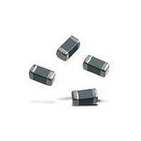
BLM18TG102TN1D Murata, BLM18TG102TN1D Datasheet - Page 180

BLM18TG102TN1D
Manufacturer Part Number
BLM18TG102TN1D
Description
EMI/RFI Suppressors & Ferrites 1K OHM LOW SPEED SIGNAL
Manufacturer
Murata
Datasheet
1.BLM18EG121SN1-D.pdf
(209 pages)
Specifications of BLM18TG102TN1D
Product
Chip Ferrite Beads
Impedance
1 KOhms
Tolerance
25 %
Maximum Dc Resistance
0.6 Ohms
Package / Case
0603 (1608 metric)
Dc Resistance Max
0.6ohm
Dc Current Rating
100mA
Ferrite Mounting
SMD
Ferrite Case Style
0603 / 1608
Rohs Compliant
Yes
Lead Free Status / RoHS Status
Lead free / RoHS Compliant
Available stocks
Company
Part Number
Manufacturer
Quantity
Price
Company:
Part Number:
BLM18TG102TN1D
Manufacturer:
MURATA
Quantity:
50 000
Part Number:
BLM18TG102TN1D
Manufacturer:
MURATA/村田
Quantity:
20 000
- Current page: 180 of 209
- Download datasheet (9Mb)
(1) Soldering Methods
Solder: Use Sn-3.0Ag-0.5Cu solder. Use of Sn-Zn based
(2) Soldering Profile
!Note
178
3. Standard Soldering Conditions
oFlow Soldering Profile
oReflow Soldering Profile
Use flow and reflow soldering methods only.
Use standard soldering conditions when soldering
common mode choke
In cases where several different parts are soldered, each
having different soldering conditions, use those
conditions requiring the least heat and minimum time.
(Sn-3.0Ag-0.5Cu Solder)
(Sn-3.0Ag-0.5Cu Solder)
• Please read rating and !CAUTION (for storage, operating, rating, soldering, mounting and handling) in this catalog to prevent smoking and/or burning, etc.
• This catalog has only typical specifications because there is no space for detailed specifications. Therefore, please review our product specifications or consult the approval sheet for product specifications before ordering.
DLM/DLP
DLW21/31
DLW5A/5B
solder will deteriorate performance of products.
If using DLP/DLM series with Sn-Zn based solder,
please contact Murata in advance.
DLM2HG
DLP31D/31S
Series
Series
coils.
220 C min.
220 C min.
Temp. (T1)
Temp. (T1)
150 C
180
150
Heating
T1
Pre-heating
30 to 60s
30 to 60s
Time. (t1)
Standard Profile
Time. (t1)
60s min.
Pre-heating
Pre-heating
chip
90s 30s
t1
Temperature
T3
T2
T2
T1
DLp Chip Common Mode Choke Coil
245 3 C
250 3 C
Peak
Temp. (T2)
(T2)
Heating
250 C
t1
t2
t2
Flux:
o Use Rosin-based flux.
o Do not use strong acidic flux (with chlorine content
o Do not use water-soluble flux.
For additional mounting methods, please contact Murata.
Heating
Standard Profile
of Reflow
Time (s)
time (s)
2 times
2 times
converting chlorine content of 0.06 to 0.1wt%.
cleaned completely with no residual flux.
exceeding 0.20wt%)
Cycle
T4
T3
In case of DLW21/31 series, use Rosin-based flux with
In case of using RA type solder, products should be
max.
max.
Time. (t2)
4 to 6s
Limit Profile
Standard Profile
Limit Profile
Standard Profile
230 C min.
230 C min.
Temp. (T3)
2 times
of Flow
Cycle
max.
Heating
60s max.
60s max.
Time. (t2)
Temp. (T3)
265 3 C
Limit Profile
Heating
Temperature
Soldering and Mounting
260 C/10s
260 C/10s
Limit Profile
Time. (t2)
Peak
5s max.
(T4)
of Reflow
2 times
2 times
Cycle
of Flow
2 times
max.
max.
Cycle
max.
Mar.28,2011
C31E.pdf
Related parts for BLM18TG102TN1D
Image
Part Number
Description
Manufacturer
Datasheet
Request
R

Part Number:
Description:
Murata Microblower 20x20 DCDC Driver Board - Samples Only
Manufacturer:
Murata

Part Number:
Description:
357-036-542-201 CARDEDGE 36POS DL .156 BLK LOPRO
Manufacturer:
Murata
Datasheet:

Part Number:
Description:
Manufacturer:
Murata
Datasheet:

Part Number:
Description:
Manufacturer:
Murata
Datasheet:

Part Number:
Description:
Manufacturer:
Murata
Datasheet:

Part Number:
Description:
Manufacturer:
Murata
Datasheet:

Part Number:
Description:
Manufacturer:
Murata
Datasheet:

Part Number:
Description:
Manufacturer:
Murata
Datasheet:

Part Number:
Description:
Manufacturer:
Murata
Datasheet:

Part Number:
Description:
BLM21BD751SN1On-Board Type (DC) EMI Suppression Filters
Manufacturer:
Murata
Datasheet:

Part Number:
Description:
BLM15AG100SN1On-Board Type (DC) EMI Suppression Filters
Manufacturer:
Murata
Datasheet:

Part Number:
Description:
NFE31PT222Z1E9On-Board Type (DC) EMI Suppression Filters
Manufacturer:
Murata
Datasheet:

Part Number:
Description:
Chip Coil
Manufacturer:
Murata
Datasheet:

Part Number:
Description:
Chip Coil
Manufacturer:
Murata
Datasheet:


