Output ..................................................................................................................................................................................................2-bit quadrature code
Closed Circuit Resistance .......................................................................................................................................................................... 3 ohms maximum
Contact Rating ................................................................................................................................................................................................ 1 mA @ 5 VDC
Insulation Resistance ........................................................................................................................................................................10 megohms @ 50 VDC
Dielectric Withstanding Voltage
Electrical Travel..................................................................................................................................................................................................... Continuous
Contact Bounce (15 RPM) ........................................................................................................................................................................5.0 ms. maximum**
RPM (Operating) ............................................................................................................................................................................................ 100 maximum**
Operating Temperature Range ...................................................................................................................................... -30 °C to +70 °C (-22 °F to +158 °F)
Storage Temperature Range ......................................................................................................................................... -40 °C to +85 °C (-40 °F to +185 °F)
Humidity ............................................................................................................................................................... MIL-STD-202, Method 103B, Condition B
Vibration .......................................................................................................................................................................................................................... 30 G
Shock ............................................................................................................................................................................................................................ 100 G
Rotational Life .................................................................................................................................................................................100,000 cycles minimum
Switch Life .........................................................................................................................................................................................20,000 cycles minimum
IP Rating ..........................................................................................................................................................................................................................IP 40
Mechanical Angle .........................................................................................................................................................................................360 ° continuous
Torque
Shaft Side Load (Static) ............................................................................................................................................................... 3.06 kgf (6.7 lbs.) minimum
Weight ............................................................................................................................................................................................ 8 gm (0.28 oz.) maximum
Terminals ................................................................................................................................................................................ Printed circuit board terminals
Terminals ................................................................................................................................................................................ Printed circuit board terminals
Hardware ..................................................................................................................... One fl at washer and one mounting nut supplied with each encoder.
Switch Type ................................................................................................................................................................... Contact Push ON Momentary SPST
Power Rating (Resistive Load) ..................................................................................................................................................................... 10 mA at 5 V DC
Switch Travel ...............................................................................................................................................................................................0.5 +0.4/-0.3 mm
Switch Actuation Force ............................................................................................................................................... 360 +153/-102 gf (5 +2.1/-1.4 oz.-in.)
Model
Terminal Confi guration
Detent Option
Standard Shaft Length
Shaft Style
Switch Confi guration
Resolution
1
How To Order
Electrical Characteristics
Environmental Characteristics
Mechanical Characteristics
Switch Characteristics
Not available with switch
Sea Level ................................................................................................................................................................................................. 50 VAC minimum
Contact Bounce............................................................................................................................................... 10~55~10 Hz / 1 min. / Amplitude 1.5 mm
Running ................................................................................................................................................................... 30.6 to 204 g-cm (0.42 to 2.83 oz.-in)
Mounting..................................................................................................................................................................... 10.2 kgf. cm (8.83 lb.-in.) maximum
Soldering Condition
2 = PC Pin Vertical/Down Facing
4 = PC Horizontal/Rear Facing
0 = No Detents
1 = 12 Detents (available with 12 pulses only)
2 = 24 Detents (available with 24 pulses only)
15 = 15 mm
20 = 20.0 mm
25 = 25.0 mm
30 = 30.0 mm
F = Insulated Flatted Shaft
S = Push Momentary Switch
N = No Switch
0012 = 12 Pulses per 360 ° Rotation
0024 = 24 Pulses per 360 ° Rotation
Wave Soldering..................................................................................... Sn95.5/Ag2.8/Cu0.7 solder with no-clean fl ux: 260 °C max. for 3-5 seconds
Hand Soldering .................................................................................................................................................................................Not recommended
1
1
**Devices are tested using standard noise reduction fi lters. For optimum performance, designers should use noise reduction fi lters in their circuits.
Features
■
■
■
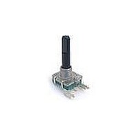
PEC16 - 16 mm Incremental Encoder
Compact design, long life and high
reliability
Low cost compared to optical type
encoders
Available in a wide variety of confi gurations
to meet many user requirements
PEC16 - 4 0 20 F - S 0012
Customers should verify actual device performance in their specifi c applications.
*RoHS Directive 2002/95/EC Jan 27, 2003 including Annex.
Quadrature Output Table
Switch Circuit
Specifi cations are subject to change without notice.
A Signal
B Signal
CW
OFF
D
D
ON
E