Output .............................................................................................................. 2-bit quadrature code, Channel A leads Channel B turning clockwise (CW)
Closed Circuit Resistance .......................................................................................................................................................................... 5 ohms maximum
Open Circuit Resistance .......................................................................................................................................................................100 K ohms minimum
Contact Rating ................................................................................................................................................. 10 milliamp @ 10 VDC or 0.1 watt maximum
Insulation Resistance (500 VDC) ................................................................................................................................................... 1,000 megohms minimum
Dielectric Withstanding Voltage (MIL-STD-202 Method 301)
Electrical Travel..................................................................................................................................................................................................... Continuous
Contact Bounce (15 RPM) ............................................................................................................................................................... 5 milliseconds maximum
RPM (Operating) ............................................................................................................................................................................................... 120 maximum
Operating Temperature Range ...................................................................................................................................... -40 ºC to +85 ºC (-40 °F to +185 °F)
Storage Temperature Range ......................................................................................................................................... -40 ºC to +85 ºC (-40 °F to +185 °F)
Humidity ............................................................................................................................................................... MIL-STD-202, Method 103B, Condition B
Vibration .......................................................................................................................................................................................................................... 15 G
Shock .............................................................................................................................................................................................................................. 50 G
Rotational Life ................................................................................................................................................................................ 200,000 shaft revolutions
IP Rating ..........................................................................................................................................................................................................................IP 40
Mechanical Angle ................................................................................................................................................................................................. Continuous
Running Torque (Detented) .............................................................................................................................................0.5 to 1.5 N-cm (0.75 to 2.25 oz-in.)
Undetented Torque .......................................................................................................................................................0.17 to 0.8 N-cm (0.25 to 1.25 oz-in.)
Weight .....................................................................................................................................................................................Approximately 8 gm (0.28 oz.)
Terminals ................................................................................................................................................................................ Printed circuit board terminals
Marking ............................................................................................................................Manufacturer’s name and trademark, part number and date code
Hardware ............................................................................................................................................................................................. No hardware supplied
This table is intended to show available outputs as currently defi ned.
RECOMMENDED INCREMENTAL CONTROL DIAGRAM FOR USE WITH A DEBOUNCE CIRCUIT
1/4 CYCLE PER DETENT
CW
Closed Circuit
Closed Circuit
Electrical Characteristics
Environmental Characteristics
Mechanical Characteristics
Quadrature Output Table
Open Circuit
Open Circuit
Sea Level ............................................................................................................................................................................................ 1,000 VAC minimum
Contact Bounce..........................................................................................................................................................................0.1 millisecond maximum
Contact Bounce..........................................................................................................................................................................0.1 millisecond maximum
Soldering Condition
Manual Soldering ...................................................96.5Sn/3.0Ag/0.5Cu solid wire or no-clean rosin cored wire; 370 °C (700 °F) max. for 3 seconds
Wave Soldering........................................................................... 96.5Sn/3.0Ag/0.5Cu solder with no-clean fl ux; 260 °C (500 °F) max. for 5 seconds
Wash Processes ...............................................................................................................................................................................Not recommended
D D D D D D D D D D D D D D D D D
Channel B
Channel A
Features
■
■
■
■
■
■
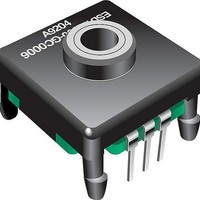
ES Series - Shaftless Contacting Encoders
7
5 ms DELAY
(MC 14490)
DEBOUNCE
.0015 f
Quadrature output
Detent option
Snap-in PC board mount
Long operating life
Incremental output
Up to 24 full quadrature outputs per
revolution
9
FULL CYCLE PER DETENT (Normally Open in Detent Shown)
CW
Closed Circuit
Closed Circuit
Open Circuit
Open Circuit
D
DECODE
LOGIC
Customers should verify actual device performance in their specifi c applications
(CUSTOMER LOGIC CIRCUITRY)
D
MAGNITUDE
DIRECTION
Channel A
Channel B
*RoHS Directive 2002/95/EC Jan 27, 2003 including Annex.
D
UP/DOWN
COUNTER
Specifi cations are subject to change without notice.
D
OUTPUT
BINARY
D