PV36W203C01B00 Murata, PV36W203C01B00 Datasheet - Page 8
PV36W203C01B00
Manufacturer Part Number
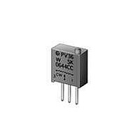
PV36W203C01B00
Description
Trimmer Resistors - Multi Turn 20Kohms 10mm Square 25turn
Manufacturer
Murata
Datasheets
1.PV36W102C01B00.pdf
(14 pages)
2.PV36W103C01B00.pdf
(22 pages)
3.PVG5A201C01R00.pdf
(90 pages)
Specifications of PV36W203C01B00
Resistance
20 KOhms
Power Rating
0.5 Watt (1/2 Watt)
Operating Temperature Range
- 55 C to + 125 C
Element Type
Cermet
Product
Multi-Turn Trimmer Potentiometers
Tolerance
10 %
Number Of Turns
25
Taper
Linear
Lead Free Status / RoHS Status
Lead free / RoHS Compliant
Available stocks
Company
Part Number
Manufacturer
Quantity
Price
Company:

Part Number:
PV36W203C01B00
Manufacturer:
MURATA
Quantity:
240 000


!Note
!Note
No.
13
14
Specifications and Test Methods
Continued from the preceding page.
Low Temperature Operation
(Only for PVF2 and
PVM4A---D01)
Rotational Life
• Please read rating and !CAUTION (for storage, operating, rating, soldering, mounting and handling) in this catalog to prevent smoking and/or burning, etc.
• This catalog has only typical specifications because there is no space for detailed specifications. Therefore, please approve our product specifications or transact the approval sheet for product specifications before ordering.
Please read rating and !CAUTION (for storage, operating, rating, soldering, mounting and handling) in this PDF catalog to prevent smoking and/or burning, etc.
This catalog has only typical specifications. Therefore, you are requested to approve our product specifications or to transact the approval sheet for product specifications before ordering.
Item
SMD Sealed Type/Lead Sealed Type Specifications and Test Methods
The trimmer potentiometer should be placed in a chamber at a temperature of -25±3°C (-55±3°C for PVM4A---
D01 series) 48±4 hours without loading. The trimmer potentiometer should be removed from the chamber, and main-
tained at a temperature of 25±5°C for 1-2 hours
1)PV-- series
Full rated continuous working voltage not exceeding the maximum rated voltage should be applied with the circuit
shown in the figure. The adjustment rotor (screw) should be continuously cycled through not less than 90% of effec-
tive-electrical rotational angle (number of turns), at the rate of 1 cycle for 5 seconds minimum to 2.5 minutes maxi-
mum for total of 200 cycles.
2) PVG3, PVG5 series
The adjustment rotor (screw) should be continuously cycled though not less than 90% of effective-electrical rotation-
al angle (number of turns), at the rate of 1 cycle for 5 seconds minimum to 2.5 minutes maximum for a total of 50
(100 for PVG5) cycles, without loading.
3) PVF2, PVM4A---D01 series
The wiper should be rotated over 90% of the effective rotational angle without loading at a speed of 10 cycles per
minute, for 100 cycles continuously.
End Terminal
Resistor 1
End Terminal
Figure 4
DC supply
End Terminal
Resistor 2 End Terminal
Test Methods
R50E13.pdf 04.6.11
81
9
Related parts for PV36W203C01B00
Image
Part Number
Description
Manufacturer
Datasheet
Request
R

Part Number:
Description:
Murata Microblower 20x20 DCDC Driver Board - Samples Only
Manufacturer:
Murata
Part Number:
Description:
357-036-542-201 CARDEDGE 36POS DL .156 BLK LOPRO
Manufacturer:
Murata
Datasheet:
Part Number:
Description:
Manufacturer:
Murata
Datasheet:
Part Number:
Description:
Manufacturer:
Murata
Datasheet:
Part Number:
Description:
Manufacturer:
Murata
Datasheet:
Part Number:
Description:
Manufacturer:
Murata
Datasheet:
Part Number:
Description:
Manufacturer:
Murata
Datasheet:
Part Number:
Description:
Manufacturer:
Murata
Datasheet:
Part Number:
Description:
Manufacturer:
Murata
Datasheet:
Part Number:
Description:
BLM21BD751SN1On-Board Type (DC) EMI Suppression Filters
Manufacturer:
Murata
Datasheet:
Part Number:
Description:
BLM15AG100SN1On-Board Type (DC) EMI Suppression Filters
Manufacturer:
Murata
Datasheet:
Part Number:
Description:
NFE31PT222Z1E9On-Board Type (DC) EMI Suppression Filters
Manufacturer:
Murata
Datasheet:
Part Number:
Description:
Chip Coil
Manufacturer:
Murata
Datasheet:
Part Number:
Description:
Chip Coil
Manufacturer:
Murata
Datasheet: