Y92P-CXT4B Omron, Y92P-CXT4B Datasheet - Page 8
Y92P-CXT4B
Manufacturer Part Number
Y92P-CXT4B
Description
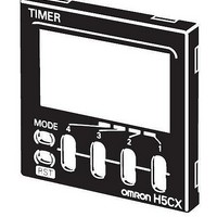
Mounting Hardware Front Panels - Rplc Black (N1.5)
Manufacturer
Omron
Type
Front Panel Replacementr
Datasheet
1.Y92P-CXT4B.pdf
(44 pages)
Specifications of Y92P-CXT4B
Color
Black
Features
Cover for Timer with 4 Digits
Product
Hardware
Lead Free Status / RoHS Status
Lead free / RoHS Compliant
For Use With
H5CX Series Timers


8
H5CX-A@-N/-L@-N
Connections
Block Diagram
Note: Basic insulation is provided between the power supply circuit and the input circuits. However, basic insulation is not provided in the
Terminal Arrangement
Confirm that the power supply meets specifications before use.
Note: Do not connect unused terminals as relay terminals.
Instantaneous
contact output
OUT1
Signal
Signal
(-)
Reset
Reset
Gate
H5CX-@D-N.
0V
6
1
Unused
0V
Internal circuit
7
2
(+)
Unused
Contact output
3
0V
4
3
2
8
3
Input circuits
2
(-)
5
(-)
4
1
1
Output circuit
6 7
9
4
(Basic insulation)
11
3
2
5
8
(+)
(+)
(–)
10
4
1
5
8
6
7
9
H5CX-A11-N/-A11D-N
H5CX-L8E-N/-L8ED-N
5
8
(+)
H5CX-L8-N/-L8D-N
H5CX-A-N/-AD-N
Internal circuit
Internal circuit
6
7
(Basic insulation)
Internal control
Terminals 1 and 6 of the H5CX-AD-N
are connected internally.
circuit
Internal circuit
Contact
output
Contact
output
Terminals 1 and 2 of the H5CX-L8D-N
are connected internally.
contact output
Time-limit
OUT2
Power supply
(See note.)
Terminals 2 and 3 of the
H5CX-A11D-N are
connected internally.
Key switch circuit
circuit
Display circuit
Transistor Output
• The transistor output of
• The diode connected to
Signal
Signal
Reset
(-)
Reset
Gate
the H5CX is insulated
from the internal circuitry
by a photocoupler, so the
transistor output can be
used as both NPN and
PNP output.
the collector of the output
transistor is used to
absorb inverted voltage
that is generated when an
inductive load is
connected to the H5CX.
0V
6
1
Unused
0V
7
2
(+)
Transistor output
Unused
3
0V
4
3
2
8
3
2
(-)
5
(-)
4
1
1
6 7
9
4
11
(+)
5
8
(+)
10
Unused
5
8
6
7
9
H5CX-A11S-N/-A11SD-N
H5CX-L8S-N/-L8SD-N
H5CX-AS-N/-ASD-N
Internal circuit
Internal circuit
Terminals 1 and 6 of the H5CX-ASD-N
are connected internally.
NPN Output
Transistor
output
Transistor
output
Terminals 1 and 2 of the H5CX-L8SD-N
are connected internally.
Power for load
Timer
+
Terminals 2 and 3 of the
H5CX-A11SD-N are
connected internally.
Power for load
Load
+
PNP Output
Load
Inductive
load
Power for load
+
Related parts for Y92P-CXT4B
Image
Part Number
Description
Manufacturer
Datasheet
Request
R

Part Number:
Description:
Mounting Hardware Front Panels - Rplc White (5Y9.2 / 0.5)
Manufacturer:
Omron
Datasheet:
Part Number:
Description:
Mounting Hardware Front Panels - Rplc Light gray (5Y7/1)
Manufacturer:
Omron
Datasheet:

Part Number:
Description:
PNL CVR LITE GRAY
Manufacturer:
Omron
Datasheet:

Part Number:
Description:
PNL CVR BLACK
Manufacturer:
Omron
Datasheet:
Part Number:
Description:
PNL CVR MED GRAY
Manufacturer:
Omron
Datasheet:

Part Number:
Description:
G6S-2GLow Signal Relay
Manufacturer:
Omron Corporation
Datasheet:
Part Number:
Description:
Compact, Low-cost, SSR Switching 5 to 20 A
Manufacturer:
Omron Corporation
Datasheet:
Part Number:
Description:
Manufacturer:
Omron Corporation
Datasheet:
Part Number:
Description:
Manufacturer:
Omron Corporation
Datasheet:
Part Number:
Description:
Manufacturer:
Omron Corporation
Datasheet:
Part Number:
Description:
Manufacturer:
Omron Corporation
Datasheet: