E39-R5 Omron, E39-R5 Datasheet
E39-R5
Specifications of E39-R5


Related parts for E39-R5


E39-R5 Summary of contents
Page 1
... E3S-AD Series includes 10 cm short range diffuse version Ordering Information SENSORS Through-beam sensors include both emitter and receiver. The polarized retroreflective sensors include E39-R1 reflector. All sensors include mounting hardware. Optional mounting brackets are available as accessories. Method of detection Sensing distance Mounting ...
Page 2
... Pulse modulated Pulse modulated Pulse modulated infrared LED (880 nm) Opaque and transparent materials 30 mm (1.18 in (3.94 x 3.94 in) minimum white mat paper 3 E3S-A Part number E39-L59 E39-S46 E39-E6 E39-R5 Y96E-43SD2 Y96E-43SD5 Y96E-43SD10 Y96E-43RD2 Y96E-43RD5 Y96E-43RD10 E39-R3 E39-R4 E39-RSA E39-RSB E39-L7 Part number E39-G2 ...
Page 3
... Lens Denatured polyarylate Case Polybutylene terephthalate (PBT) Bracket Stainless steel Mounting Either side surface with two threaded holes. Bracket E39-L69 for horizontal or E39-L70 for vertical sensors and hardware included. Connections Prewired 2 m (6.56 ft) long cable Connector M12 threaded connector, 4 pin Weight ...
Page 4
E3S-A Operation OUTPUT CIRCUIT DIAGRAMS NPN Cable Type Through-beam emitter E3S-AT11, E3S-AT61 Red (Brown Main VDC circuit Black (Blue) NOTE: IEC colors are shown in parentheses. NPN Cable Type with Self-Diagnostic Functions Through-beam emitter E3S-AT21, E3S-AT71 Red ...
Page 5
E3S-A PNP Cable Type Through-beam emitter E3S-AT31, E3S-AT81 Red (Brown) Main circuit VDC Black (Blue) NOTE: IEC colors are shown in parentheses. PNP Cable Type with Self-Diagnostic Functions Through-beam emitter E3S-AT41, E3S-AT91 Red (Brown ...
Page 6
... E3S- cm) 100 50 20 E3S- E3S- Distance (cm) E3S-AR 1 (With Reflector: E39-R1) 100 Operating level 1 0 0.2 0.4 0.6 0.8 1 1.2 1.4 1.6 1.8 2 2.2 2.4 2.6 Distance (m) 7 E3S-A E3S-AD 1, -AD 2 (Detection of Black Paper) 100 Sensing object: black 50 (E3S- E3S- cm) 10 ...
Page 7
E3S-A OPERATING RANGE Parallel Operating Range (Typical) E3S- Distance X ( OPERATING RANGE (typical) E3S-AD 3, E3S-AD 8 (Left and Right) 60 ...
Page 8
E3S-A Dimensions Unit: mm (inch) SENSORS E3S-AD11, E3S-AD12, E3S-AD13, E3S-AD31, E3S-AD32, E3S-AD33 (see note 1), E3S-AD21, E3S-AD22, E3S-AD23, E3S-AD41, E3S-AD42, E3S-AD43 Receiver: E3S-AT11, E3S-AT31 (see note 2) E3S-AT21, E3S-AT41 Light indicator (red) 12.9 12.4 12 (0.49) Lens ...
Page 9
E3S-A SENSORS (continued) E3S-AD16, E3S-AD17, E3S-AD18, E3S-AD36, E3S-AD37, E3S-AD38 Receiver: E3S-AT16, E3S-AT36 Light indicator (red) 12.9 12.4 12 (0.49) Lens Optical axis 1 10.5 E3S-AD66, E3S-AD67, E3S-AD68, E3S-AD86, E3S-AD87, E3S-AD88 Receiver: E3S-AT66, E3S-AT86 Lens 7 ...
Page 10
E3S-A SENSORS (continued) E3S-AR61, E3S-AR81 E3S-AR71, E3S-AR91 12.4 (0.49) Light indicator (red) Stability indicator (green) Sensitivity adjuster (white) 5.9 OFF-delay time adjuster/turbo switch (black) 7 23.3 Turn to adjust the (0.92) OFF-delay time: 5.5 push to switch turbo function E3S-AR16, ...
Page 11
... Face View, Female Connector 90 Aluminum coupling nut 1. +V Red (Brown) NOTES: *Not used on 3-wire models. IEC colors are shown in parentheses. Aluminum coupling nut E39-L7 Reflector Adapter for E39-R1 Reflector 39.3 (1.55) 34 (1.339) 7 (0.276) 34 (1.34) 59.9 (2.36) 52 (2.07) 8 (0.32) Two M3 12 E3S ...
Page 12
... Two M3 1.2 E39-R4 Optional Mini-reflector 13.7 4 9.7 0 0.1 2 E39-RSA Optional Adhesive-backed Reflector Four 1R OPTICAL AXIS CONFIRMATION REFLECTOR E39-R5 for E3S-A Sensors 59.9 25 Dimensions with E39-L54 Mounting Bracket (included) 20 0.2 Two M3 25 41.8 25.4 0.1 10.1 1.2 4.9 4 1.4 Two, 2.2 dia. ...
Page 13
... A = Slit width MOUNTING SPACER FOR CONNECTOR-TYPE SENSORS E39-L60 Spacer 11.75 5 MOUNTING BRACKETS (supplied with sensors) E39-L69 Mounting Bracket 10.7 16.5 3.2 4 10.7 1.2 E39-E6 Mutual Interference Filter 6.8 2 6.5 6.5 2.5 3.4 dia. E39-L70 Mounting Bracket 16.5 3.2 7.2 1.2 Two screws 14 E3S-A 11 ...
Page 14
... E3S-A E39-L59 OPTIONAL VERTICAL MOUNTING BRACKET 15.7 Mounting bracket (E39-L59) 3 5.5 3.2 3.2 20 34.5 E39-G2 SENSITIVITY ADJUSTER KNOB MOUNTING BRACKET NOTCH Each mounting bracket slot has a notch to provide a center position for aligning the sensor parallel to the bracket. This ensures that the beam is aligned with the mounting surface ...
Page 15
E3S-A Installation SENSITIVITY ADJUSTMENT Steps Step 1 Function Determine Position A Sensing Photoelectric sensor Condition Sensing object Sensitivity A adjuster Max Min Indicators ON OFF STABILITY (green) Place target at the desired Procedure sensing distance. Set sensitivity adjuster to the ...
Page 16
E3S-A Self-Diagnostic Function With this function, the E3S-A sensor checks changes in environmental conditions (especially a change in the ambient temperature) and self-diagnoses the resistance against the changes. The result is shown by the indicators or an output signal. Amount ...
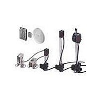
Page 17
... OPTICAL AXIS CONFIRMATION REFLECTOR E39-R5 Use this attachment when the set distance is long and adjustment is mechanically difficult with a sensing object. ...
Page 18
... One East Commerce Drive Schaumburg, IL 60173 1-800-55-OMRON Cat. No. CEDSAX4 11/01 OMRON ON-LINE Global - http://www.omron.com USA - http://www.omron.com/oei Canada - http://www.omron.com/oci Specifications subject to change without notice. E3S-A OMRON CANADA, INC. 885 Milner Avenue Scarborough, Ontario M1B 5V8 416-286-6465 Printed in the U.S.A. ...