G9EA-1-B-CA-DC12 Omron, G9EA-1-B-CA-DC12 Datasheet - Page 18
G9EA-1-B-CA-DC12
Manufacturer Part Number
G9EA-1-B-CA-DC12
Description
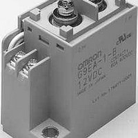
General Purpose / Industrial Relays 12VDC 100A SCRW TERM
Manufacturer
Omron
Series
G9EAr
Datasheets
1.G9EA-1-B-CA-DC12.pdf
(24 pages)
2.G9EA-1_DC24.pdf
(10 pages)
3.G9EA-1-B-CA-DC12.pdf
(3 pages)
Specifications of G9EA-1-B-CA-DC12
Coil Resistance
28.8 Ohms
Contact Form
SPST - NO
Coil Voltage
12 VDC
Contact Rating
10 A
Coil Termination
Screw Terminals
Contact Termination
Screw
Power Consumption
5 W
Coil Current
417 mA
Relay Type
High Voltage
Coil Voltage Vdc Nom
12V
Contact Current Max
30A
Contact Voltage Dc Nom
400V
Contact Configuration
SPST-NO
Coil Type
DC
Current, Rating
60 A
Dielectric Rating
2500 VAC
Dimensions
2.87 " L x 1.42 " W x 2.64 " H
Function
Power
Material, Contact
Ag Alloy
Resistance, Coil
12.8 Ohms
Resistance, Contact
30 Milliohms (Max.)
Standards
UL, CSA
Temperature, Operating, Maximum
50 °C
Temperature, Operating, Minimum
-40 °C
Termination
Screw
Voltage, Control
12 VDC
Voltage, Drop, On-state
0.1 V (Max.)
Voltage, Rating
400 VDC
Lead Free Status / RoHS Status
Lead free / RoHS Compliant
Lead Free Status / RoHS Status
Lead free / RoHS Compliant, Lead free / RoHS Compliant


Specifications
■ Ratings
Coil
Note: 1. The figures for the rated current and coil resistance are for a coil temperature of 23°C and have a tolerance of ±10%.
Contacts
■ Characteristics
Note: 1. The above values are initial values at an ambient temperature of 23°C unless otherwise specified.
18
12 VDC
24 VDC
48 VDC
60 VDC
100 VDC
Rated load
Rated carry current
Maximum switching voltage
Maximum switching current
Contact resistance (See note 2.)
Contact voltage drop
Operate time
Release time
Insulation resistance
(See note 3.)
Dielectric strength
Impulse withstand voltage (See note 4.)
Vibration resistance
Shock resistance
Mechanical endurance (See note 5.)
Electrical endurance (resistive load) (See note 6 and 7.)
Short-time carry current
Maximum interruption current (See note 7.)
Overload interruption (See note 7.)
Ambient operating temperature
Ambient operating humidity
Weight (including accessories)
Rated voltage
2. The figures for the operating characteristics are for a coil temperature of 23°C.
3. The figure for the maximum voltage is the maximum voltage that can be applied to the relay coil.
2. The contact resistance was measured with 1 A at 5 VDC using the voltage drop method.
3. The insulation resistance was measured with a 500-VDC megohmmeter.
4. The impulse withstand voltage was measured with a JEC-212 (1981) standard impulse voltage waveform (1.2 × 50 µs).
5. The mechanical endurance was measured at a switching frequency of 3,600 operations/hr.
6. The electrical endurance was measured at a switching frequency of 60 operations/hr.
7. These values are for when a varistor is used as the protective circuit against reverse surge in the relay coil. Using a diode will reduce the
switching characteristics.
DC Power Relays (25-A Models)
Item
166.7 mA
83.3 mA
41.7 mA
33.3 mA
20 mA
Rated current
Between coil and contacts
Between contacts of the same polarity
Between coil and contacts
Between contacts of the same polarity
Destruction
Malfunction
Destruction
Malfunction
Item
25 A at 250 VDC
25 A
250 V
25 A
72 Ω
288 Ω
1,152 Ω
1,800 Ω
5,000 Ω
Coil resistance
Resistive load
G9EB-1(-B)
G9EB-1
75% max. of rated
voltage
Must-operate
30 mΩ max.
0.1 V max. (for a carry current of 25 A)
30 ms max.
15 ms max.
1,000 MΩ min.
1,000 MΩ min.
2,500 VAC, 1 min
2,500 VAC, 1 min
4,500 V
10 to 55 to 10 Hz, 0.75-mm single amplitude (Acceleration: 2.94 to 88.9 m/s
10 to 55 to 10 Hz, 0.75-mm single amplitude (Acceleration: 2.94 to 88.9 m/s
490 m/s
100 m/s
100,000 operations min.
250 VDC, 25 A, 30,000 ops. min.
50 A (5 min), 40 A (10 min)
100 A at 250 VDC (5 times)
−40 to 70°C (with no icing or condensation)
5% to 85%
Approx. 135 g
50 A at 250 VDC (50 times min.)
voltage
2
2
10% min. of rated
voltage
Must-release
voltage
G9EB-1-B
130% of rated volt-
age (at 23°C within
10 minutes)
Maximum voltage
(See note 3.)
Approx. 2 W
consumption
Power
2
2
)
)