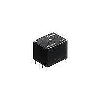
ACT212 Panasonic, ACT212 Datasheet - Page 3

ACT212
Manufacturer Part Number
ACT212
Description
General Purpose / Industrial Relays 12VDC 1 FORM C X 2 20A 8 TERMINALS
Manufacturer
Panasonic
Datasheet
1.ACT512.pdf
(5 pages)
Specifications of ACT212
Contact Form
Dual 1 Form C
Coil Voltage
12 VDC
Contact Rating
20 A at 14 VDC, 10 A at 14 VDC
Coil Termination
Solder Terminal
Contact Termination
Solder Terminal
Mounting Style
Through Hole
Power Consumption
800 mW
Contact Material
Silver Alloy
Coil Current
66.7 mA
Coil Resistance
180 Ohms
Coil Type
Standard
Lead Free Status / RoHS Status
Lead free / RoHS Compliant
Available stocks
Company
Part Number
Manufacturer
Quantity
Price
Company:
Part Number:
ACT212
Manufacturer:
FREESCALE
Quantity:
560
Company:
Part Number:
ACT212
Manufacturer:
Panasonic Electric Works
Quantity:
135
Part Number:
ACT212
Manufacturer:
NAIS
Quantity:
20 000
Company:
Part Number:
ACT212 12V
Manufacturer:
PANASONIC
Quantity:
5 400
Company:
Part Number:
ACT212-12V
Manufacturer:
NVIS
Quantity:
5 400
Company:
Part Number:
ACT212-M41-12V
Manufacturer:
PANASONIC
Quantity:
5 400
Part Number:
ACT212M19-12V
Manufacturer:
NAIS
Quantity:
20 000
3. Slim 1c type
* Dimensions (thickness and width) of terminal specified in this catalog is measured before pre-soldering.
EXAMPLE OF CIRCUIT
Forward/reverse control circuits of DC
motor for power windows
REFERENCE DATA
1-(1). Coil temperature rise (at room
temperature
Sample: ACT212, 3pcs.
Contact carrying current: 0A, 10A, 20A
3. Ambient temperature and operating voltage
range
Intervals between terminals is measured at A surface level.
140
120
100
80
60
40
20
40
35
30
25
20
15
10
0
5
0
–40 –20
Pick-up voltage (Cold start)
12
0
Ambient temperature, C
Coil applied voltage, V
20
40
14
60
3.15
.124
1.45
.057
80 85
.138
1.25
.049
3.5
13.5
.531
Sealed by epoxy resin
16
0.65
.006
100
.039
.016
All Rights Reserved © COPYRIGHT Panasonic Electric Works Co., Ltd.
.016
20A
10A
0A
0.4
0.4
1
120
.039
.236
6
1
17.4
.685
.374
9.5
.591
15
1-(2). Coil temperature rise (at 85 C
Sample: ACT212, 3pcs.
Contact carrying current: 0A, 10A, 20A
4. Distribution of pick-up and drop-out voltage
Sample: ACT212, 40pcs.
.039
1
12 V DC
140
120
100
80
60
40
20
50
40
30
20
10
.012
0
0
0.3
0 1
1.5
Max. 1.0
SW A
4.3
.169
12
2.0 2.5 3.0 3.5
.039
*A
.031
0.8
Dimension:
Max. 1mm
1 to 3mm
Min. 3mm
Pre-soldering
Coil applied voltage, V
NO
NC
.016
0.4
.283
7.2
14
Voltage, V
4.0
COM
4.5 5.0
.016
0.4
Pick-up voltage
Drop-out voltage
.039 to .118
.118
.039
5.5 6.0 6.5 7.0 7.5
M
inch:
: Power window motor
inch:
16
M
185
20A
10A
0A
F)
inch: 0.2
COM
Tolerance
0.1
0.3
SW B
NO
NC
2. Max. switching capability (Resistive load,
initial)
5. Distribution of operate and release time
Sample: ACT212, 40pcs.
* Without diode
.004
.008
.012
3-1.4 dia.
3-.055 dia.
3.15
.124
0.65
.026
60
50
40
30
20
10
35
20
25
20
15
10
5
0
PC board pattern (Bottom view)
0
1.0 1.1 1.2 1.3 1.4 1.5 1.6 1.7 1.8 1.9 2.0
0
Schematic (Bottom view)
COM
.236
10
6
.374
9.5
Operate and release time, ms
NO
(N.O. side: room temperature)
.591
15
Switching current, A
20
Tolerance: 0.1
NC
CT (ACT)
30
Operate time
Release time
COIL
4.3
.169
40
2-1.1
2-.043
mm
+0.1
0
50
+0.04
0
dia.
.004
inch
dia.


