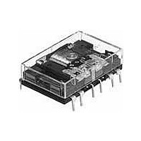
NC4D-JP-DC12V Panasonic, NC4D-JP-DC12V Datasheet - Page 13

NC4D-JP-DC12V
Manufacturer Part Number
NC4D-JP-DC12V
Description
General Purpose / Industrial Relays 5A 12VDC 4PDT FLAT PCB
Manufacturer
Panasonic
Datasheet
1.N-TC-48.pdf
(14 pages)
Specifications of NC4D-JP-DC12V
Contact Form
4 Form C
Coil Voltage
12 VDC
Contact Rating
5 A at 250 VAC
Coil Termination
Solder Terminal
Contact Termination
Solder Terminal
Mounting Style
Through Hole
Power Consumption
360 mW
Contact Material
Gold Clad Silver Nickel
Coil Resistance
400 Ohms
Coil Type
Single Side Stable
Lead Free Status / RoHS Status
Lead free / RoHS Compliant
Available stocks
Company
Part Number
Manufacturer
Quantity
Price
Company:
Part Number:
NC4D-JP-DC12V
Manufacturer:
ARM
Quantity:
250
Company:
Part Number:
NC4D-JP-DC12V
Manufacturer:
Panasonic
Quantity:
12 000
NC
Slim type socket
for solder terminal
NC2-SS
Slim type socket
for solder terminal
NC4-SS
Slim type socket
for PC board
NC2-PS
Slim type socket
for PC board
NC4-PS
B
B
A
Note: NC2-SS is as shown in the diagram above except that terminals marked with “ ” are not present.
Note: NC4-SS is as shown in the diagram above except that terminals marked with “ ” are not present.
Note: NC2-PS is as shown in the diagram at left except that terminals marked with “ ” are not present.
Note: NC4-PS is as shown in the diagram at left except that terminals marked with “ ” are not present.
A
1.177
CAD Data
CAD Data
CAD Data
CAD Data
29.9
1.732
44.0
12.6
.496
1.177
29.9
12.6
.496
12.6
.496
1.732
44.0
12.6
.496
All Rights Reserved © COPYRIGHT Panasonic Electric Works Co., Ltd.
External dimensions
External dimensions
20.4
.803
20.4
.803
.154
.154
1.142
3.9
3.9
29.0
20.4
.803
20.4
.803
.154
.154
.039
3.9
3.9
.039
.339 .315
.339
1.0
8.6
1.0
8.6
External dimensions
External dimensions
.315
.039
.039
.339
.339
8.0
8.0
1.0
1.0
8.6
8.6
4.6
.181
4.6
.181
30.48
1.200
1.098
27.9
20.32
.800
20.32
.800
10.16
1.098
.400
10.16
27.9
.400
20.32
.800
5.08
.200
5.08
.200
1.654
42.0
10.16
.400
30.48
1.200
5.08
.200
20.32
11.2
.441
7.62
.300
.800
11.2
.441
7.62
.300
10.16
.400
11.2
.441
7.62
.300
5.08
.200
5.08
.200
5.08
.200
15.24
.600
1.000
5.08
.200
11.5
.453
15.24
25.4
7.62
.300
.600
35.56
1.400
15.24
.600
42.0
1.654
5.08
.200
15.24 35.56
.600
1.000
25.4
Chassis cutout
Chassis cutout
1.400
11.5
.453
11.5
.453
1.118
1.673
42.5
28.4
Notes: 1. Suitable chassis
Notes: 1. Suitable chassis
2.54 3
.100 3
2.54
.100
2.8 dia.
.110 dia.
2.54 3
.100 3
2.8 dia.
.110 dia.
PC board pattern
2.54
.100
PC board pattern
2.54
.100
2. Once the socket is
2. Once the socket is
9
thickness is 1.0 to 2.0
mm
inserted from above
into the mounting
holes, the relay will
snap in to clips rising
from either side at (A)
and (B) by pushing.
thickness is 1.0 to 2.0
mm
inserted from above
into the mounting
holes, the relay will
snap in to clips rising
from either side at (A)
and (B) by pushing.
2.54
.100
8
10
7
11
7
.039 to .079
.039 to .079
.020
11
0.5
6
16-1.2 dia. hole
16-.047 dia.
.020
12
0.5
5
6
10-1.2 dia. hole
10-.047 dia.
12
5
13
4 3
13
4
14
3
14
2
2
inch.
inch.
15
1
16


