G5V-13-DC24 Omron, G5V-13-DC24 Datasheet - Page 2
G5V-13-DC24
Manufacturer Part Number
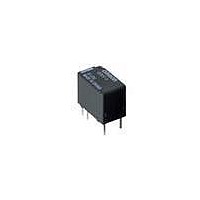
G5V-13-DC24
Description
Low Signal Relays - PCB Ultra Mini Hi-Sens SPDT Dbl Ct 24DC
Manufacturer
Omron
Datasheet
1.G5V-13-DC12.pdf
(3 pages)
Specifications of G5V-13-DC24
Contact Form
SPDT
Coil Voltage
24 VDC
Coil Current
6.25 mA
Coil Type
Relay
Power Consumption
150 mW
Contact Carry Current
2 A
Termination Style
Solder Pin
Maximum Switching Current
1 A
Lead Free Status / RoHS Status
Lead free / RoHS Compliant
Available stocks
Company
Part Number
Manufacturer
Quantity
Price
Company:

Part Number:
G5V-13-DC24
Manufacturer:
OMRON
Quantity:
5 000


G5V-1
I
Note:
I
Note:
Note:
I
UL1950 (File No. E41515)/CSA C22.2 No.0, No.14 (File No. LR31928)
Load
Rated load
Contact material
Rated carry current
Max. switching voltage
Max. switching current
Max. switching power
Failure rate (reference value)
(See note.)
Contact resistance (See note 1.)
Operate time (See note 2.)
Release time (See note 2.)
Max. operating frequency
Insulation resistance (See note 2.)
Dielectric strength
Impulse withstand voltage
Vibration resistance
Shock resistance
Endurance
Ambient temperature
Ambient humidity
Weight
G5V-1
Approved Standards
Characteristics
Contact Ratings
Model
P level:
This value was measured at a switching frequency of 120 operations/min and the criterion of contact resistance is 100 Ω . This value
may vary depending on the operating environment. Always double-check relay suitability under actual operating conditions.
The values here are initial values.
1. The contact resistance was measured with 10 mA at 1 VDC with a voltage drop method.
2. Values in parantheses are actual values.
3. The insulation resistance was measured with a 500-VDC megohmmeter between coil and contacts and a 250-VDC megohm-
meter between contacts with the same polarity applied to the same parts as those used for checking the dielectric strength.
λ
60
SPDT
= 0.1 x 10
Contact form
–6
/operation
3 to 24 VDC
Coil ratings
Resistive load (cos φ = 1)
0.5 A at 125 VAC; 1 A at 24 VDC
Ag + Au-Alloy
2 A
125 VAC, 60 VDC
1 A
62.5 VA, 30 W
1 mA at 5 VDC
100 m Ω max.
5 ms max. (approx. 2.5 ms)
5 ms max. (approx. 0.9 ms)
Mechanical: 36,000 operations/hr
Electrical: 1,800 operations/hr (under rated load)
1,000 M Ω min. (at 500 VDC between coil and contacts, at 250 VDC between contacts of same
polarity.)
1,000 VAC, 50/60 Hz for 1 min between coil and contacts
400 VAC, 50/60 Hz for 1 min between contacts of same polarity
1,500 V (10 x 160 µs) between coil and contacts (conforms to FCC Part 68)
Destruction: 10 to 55 to 10 Hz, 1.65-mm single amplitude (3.3-mm double amplitude)
Malfunction: 10 to 55 to 10 Hz, 1.65-mm single amplitude (3.3-mm double amplitude)
Destruction: 1,000 m/s
Malfunction: 100 m/s
Mechanical: 5,000,000 operations min. (at 18,000 operations/hr)
Electrical: 100,000 operations min. (under rated load, at 1,800 operations/hr)
Operating: − 40°C to 70°C (with no icing)
Operating: 5% to 85%
Approx. 2 g
0.5 A, 125 VAC (general use)
0.3 A, 110 VDC (resistive load)
1 A, 30 VDC (resistive load)
2
2
Contact ratings
G5V-1
47
Related parts for G5V-13-DC24
Image
Part Number
Description
Manufacturer
Datasheet
Request
R

Part Number:
Description:
Low Signal Relay
Manufacturer:
Omron
Datasheet:
Part Number:
Description:
Low Signal Relays - PCB Ultra Mini Hi-Sens SPDT Dbl Ct 12DC
Manufacturer:
Omron
Datasheet:
Part Number:
Description:
Low Signal Relay
Manufacturer:
Omron
Datasheet:

Part Number:
Description:
RELAY DPDT 2A 48VDC PCB
Manufacturer:
Omron
Datasheet:

Part Number:
Description:
RELAY PCB DPDT 2A 3VDC SEALED
Manufacturer:
Omron
Datasheet:

Part Number:
Description:
RELAY DPDT 2A 12V 288 OHM COIL
Manufacturer:
Omron
Datasheet:
Part Number:
Description:
RELAY DPDT 2A 24V 1152 OHM COIL
Manufacturer:
Omron
Datasheet:
Part Number:
Description:
RELAY DPDT 2A 5V 50 OHM COIL
Manufacturer:
Omron
Datasheet:

Part Number:
Description:
RELAY PCB DPDT 2A 6VDC
Manufacturer:
Omron
Datasheet:
Part Number:
Description:
LOW SIGNAL RELAY
Manufacturer:
Omron
Datasheet:

Part Number:
Description:
RELAY PC MNT DPDT
Manufacturer:
Omron
Datasheet:

Part Number:
Description:
Manufacturer:
Omron Corporation
Datasheet: