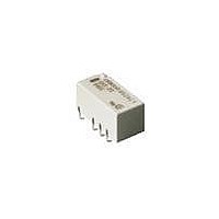
G6SK-2F-DC24 Omron, G6SK-2F-DC24 Datasheet

G6SK-2F-DC24
Specifications of G6SK-2F-DC24
Available stocks
Related parts for G6SK-2F-DC24
G6SK-2F-DC24 Summary of contents
Page 1
... Therefore not marked on the relay case. 3. Dual coil latching models are available with a High-sensitivity coil. (140 mW; 200 mW for DC24) When ordering High-sensitivity dual coil latching models, add "-H” to the model number. Example: G6SK-2G-H-TR DC5 High-sensitivity coil Model Number Legend ...
Page 2
... Armature OFF 3 33.3 90 0.108 4.5 22.2 203 0.27 5 20.0 250 0.36 12 8.3 1,440 2.12 24 6.3 3,840 5.80 G6SK - Standard Dual Coil Latching (G6SK-2F, G6SK-2G, G6SK-2) Rated Rated Coil voltage current resistance (VDC) (mA) (Ω) Armature 3 66.6 45 0.045 4.5 44.4 101 0. 125 ...
Page 3
... G 2 750 m/s ; approx -40 to +85°C with no icing; -40 to +70°C with no icing (G6SK, DC24 coil 85% RH 100,000,000 operations min. (at 36,000 operations/hour) 100,000 operations min. (2A@30VDC, resistive; 1,200 ops/hr.) 100,000 operations min. (0.5A@125VAC, resistive) See “Characteristic Data” ...
Page 4
... Breakdown voltage (V) Between coil and contacts Single Coil Latching Dual Coil Latching G6SU G6SK 12 VDC max. G6SK 24 VDC Ambient temperature (° 1000 1500 2000 2500 3000 3500 Breakdown voltage (V) Between contacts of different poles Between contacts of same pole. ...
Page 5
Impulse Withstand Voltage (Standard Version, Non-latching ms 3500 4000 4500 5000 5500 6000 Breakdown voltage (V) Between coil and contacts Impulse Withstand Voltage (European version ms ...
Page 6
Dimensions Note: 1. All units are in millimeters unless otherwise indicated. 2. Coplanarity is 0.1 mm max. ■ Standard G6S-2F, G6S-2F-Y Tolerance: ±0.3 G6S-2G, G6S-2G-Y Tolerance: ±0.3 G6S-2, G6S-2-Y Tolerance: ±0.3 G6S 100 Low Signal Relay Terminal Arrangement/ Footprint Internal ...
Page 7
Single Coil Latching G6SU-2F Tolerance: ±0.3 G6SU-2G Tolerance: ±0.3 G6SU-2 Tolerance: ±0.3 Terminal Arrangement/ Internal Connections (Top View) 7.3+0.2 Orientation mark Terminal Arrangement/ 7.3+0.2 Internal Connections (Top View) Orientation mark Terminal Arrangement/ Internal Connections (Bottom View) Orientation mark Low ...
Page 8
... Dual Coil Latching G6SK-2F Tolerance: ±0.3 G6SK-2G Tolerance: ±0.3 G6SK-2 Tolerance: ±0.3 Recommended Soldering Method (1) IRS Method (Mounting Solder: Lead) Soldering Soldering 220 to 240 180 to 200 Preheating Preheating 150 90 to 120 Time (s) G6S 102 Low Signal Relay Terminal Arrangement/ Internal Connections ...
Page 9
... When ordering, add “TR” before the rated coil voltage (e.g., G6S-2F-TR-DC12) Note not part of the relay model number and will not be marked on the relay. 29.5±1.0 G6S-2F, G6SU-2F, G6SK-2F, G6S-2F-Y 25.5±0.5 330 80 G6S-2G, G6SU-2G, G6SK-2G, G6S-2G-Y Coil rating Contact ratings VDC VDC (Resistive) 0 110 VDC (Resistive VDC ...
Page 10
... Be sure to adjust the level of the molten solder so that the solder will not overflow onto the PCB. Claw Securing Force During Automatic Mounting During automatic insertion of Relays, be sure to set the securing force of each claw to the following so that the Relay’s characteristics will be maintained. ...
Page 11
... Seller within 30 days of receipt of shipment. III. PRECAUTIONS 1. Suitability THE BUYER’S SOLE RESPOINSIBILITY TO ENSURE THAT ANY OMRON PRODUCT IS FIT AND SUFFICIENT FOR USE IN A MOTORIZED VEHICLE APPLICATION. BUYER SHALL BE SOLELY RESPONSIBLE FOR DETERMINING APPROPRIATENESS OF THE PARTICULAR PRODUCT WITH RESPECT TO THE BUYER’ ...
Page 12
... THE OMRON PRODUCT IS PROPERLY RATED AND INSTALLED FOR THE INTENDED USE WITHIN THE OVERALL EQUIPMENT OR SYSTEM. Complete “Terms and Conditions of Sale” for product purchase and use are on Omron’s website at http://www.components.omron.com – under the “About Us” tab, in the Legal Matters section. ...


