G6S-2F-Y DC5 Omron, G6S-2F-Y DC5 Datasheet - Page 5
G6S-2F-Y DC5
Manufacturer Part Number
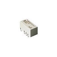
G6S-2F-Y DC5
Description
Low Signal Relays - PCB EN60950 SMT Relay
Manufacturer
Omron
Series
G6Sr
Datasheet
1.G6S-2F-Y_DC5.pdf
(12 pages)
Specifications of G6S-2F-Y DC5
Contact Form
2 Form C (DPDT)
Coil Voltage
5 V
Coil Current
28.1 mA
Power Consumption
140 mW
Contact Carry Current
2 A
Termination Style
Solder Tail
Maximum Switching Current
2 A
Contact Rating
2 A
Lead Free Status / RoHS Status
Lead free / RoHS Compliant
Other names
BY DC5 G6S2FY G6S2FYDC5BYOMR OMR


G6S
Engineering Data
Maximum Switching Power
Reference Data
Ambient Temperature vs. Switching Current
Single-side Stable
Recommended Soldering Time vs. Surface PCB Temperature
(1) IRS Method (Mounting Solder: Lead)
220 to
180 to
240
200
150
24 VDC
(G6S-Y)
24 VDC
(G6S-Y, 12 VDC
max.)
DC resistive load
Ambient temperature (°C)
Switching voltage (V)
Preheating
AC resistive load
Preheating
90 to 120
12 VDC max.
Soldering
Soldering
20 to 30
Time (s)
Ambient Temperature vs.
Maximum Coil Voltage
Single-side Stable
Single-winding Latching
Double-winding Latching
Note: The maximum coil voltage refers to the maximum value in a varying range of
operating power voltage, not a continuous voltage.
24 VDC
(G6S-Y, 12 VDC max.)
Ambient temperature (°C)
Ambient temperature (°C)
(2) IRS Method (Mounting Solder: Lead-free)
Note: The temperature profile indicates the
G6SK
24 VDC
250 max.
12 VDC max.
230
180
150
temperature of the relay terminal section.
24 VDC
(G6S-Y)
G6SU
12 VDC max.
Upper surface of case (peak):
255˚C max.
G6SU
24 VDC
G6SK
12 VDC max.
Preheating
120 max.
Single-winding Latching
Double-winding Latching
Soldering
30 max.
Relay
terminal
section
Time (s)
Ambient temperature (°C)
G6SK
12 VDC
max.
G6SK
24 VDC
G6SU
G6S
5
Related parts for G6S-2F-Y DC5
Image
Part Number
Description
Manufacturer
Datasheet
Request
R

Part Number:
Description:
EN60950 SMT Relay Tape & Reel
Manufacturer:
Omron
Datasheet:
Part Number:
Description:
EN60950 SMT Relay
Manufacturer:
Omron
Datasheet:
Part Number:
Description:
EN60950 SMT Relay Tape & Reel
Manufacturer:
Omron
Datasheet:
Part Number:
Description:
EN60950 SMT Relay
Manufacturer:
Omron
Datasheet:
Part Number:
Description:
EN60950 SMT Relay
Manufacturer:
Omron
Datasheet:
Part Number:
Description:
EN60950 SMT Relay Tape & Reel
Manufacturer:
Omron
Datasheet:
Part Number:
Description:
EN60950 SMT Relay Tape & Reel
Manufacturer:
Omron
Datasheet:
Part Number:
Description:
EN60950 SMT Relay Tape & Reel
Manufacturer:
Omron
Datasheet:
Part Number:
Description:
EN60950 SMT Relay Tape & Reel
Manufacturer:
Omron
Datasheet:
Part Number:
Description:
EN60950 SMT Relay Tape & Reel
Manufacturer:
Omron
Datasheet:
Part Number:
Description:
EN60950 SMT Relay
Manufacturer:
Omron
Datasheet:
Part Number:
Description:
EN60950 SMT Relay
Manufacturer:
Omron
Datasheet:
Part Number:
Description:
EN60950 SMT Relay
Manufacturer:
Omron
Datasheet:

Part Number:
Description:
Low Signal Relays - PCB EN60950 SMT Relay
Manufacturer:
Omron
Datasheet:
Part Number:
Description:
EN60950 SMT RELAY
Manufacturer:
Omron
Datasheet: