P7S-14F-END-DC24 Omron, P7S-14F-END-DC24 Datasheet
P7S-14F-END-DC24
Specifications of P7S-14F-END-DC24


Related parts for P7S-14F-END-DC24


P7S-14F-END-DC24 Summary of contents
Page 1
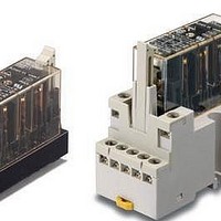
... Relays with Forcibly Guided Contacts Type Poles Standard 6 poles Sockets Type Track-mounting Common for track mounting and screw mounting Back-mounting PCB terminals Contact configuration Rated voltage 4PST-NO, DPST-NC 24 VDC 3PST-NO, 3PST-NC Rated voltage 24 VDC --- CSM_G7S_DS_E_5_1 Model G7S-4A2B G7S-3A3B Model P7S-14F-END P7S-14P-E 1 ...
Page 2
... Maximum switching current Characteristics of Sockets Model Continuous current P7S-14 Note: Use the P7S-14F-END in the ambient humidity range 85%. * The insulation resistance was measured with a 500-VDC megohmmeter at the same locations as the dielectric strength was measured. Characteristics Contact resistance *1 Operating time *2 Release time *2 Mechanical ...
Page 3
... Engineering Data Durability Curve (Rated Resistive Load resistive load Contact current (A) Dimensions Relays with Forcibly Guided Contacts G7S-4A2B G7S-3A3B 62 max Terminal Arrangement/Internal Connection Diagram (Bottom View) 22.5 max. G7S-4A2B VDC max. 0.5 10.8 G7S-3A3B 5 min. 1 VDC 14 G7S (Unit: mm) Mounting Hole Dimensions 8 ± ...
Page 4
... Sockets Track-mounting Socket P7S-14F-END Indicator 40 max. 33±0.1 5 (5) Back-mounting Socket (PCB Terminals) P7S-14P-E 70.5 max. 28 ±0.2 23.5 max. Two, 6.5 dia x 8 depth 6 5×7=35 Fourteen, M3.0 × 7.5 3.1 5.9 90.5 max. Terminal Arrangement/Internal Connection Diagram (Bottom View) With G7S-4A2B mounted With G7S-3A3B mounted 57 max ...
Page 5
... Stranded wire: 0. Solid wire: 1.0 to 1.5 mm • Tighten each screw of the P7S-14F-END to a torque of 0.78 to 0.98 N·m. • Refer to the internal connections diagram of the G9S Safety Relay Unit for an application example of the G7S. • Wire the terminals correctly with no mistakes in coil polarity, otherwise the G7S will not operate ...
Page 6
... Please read and understand this catalog before purchasing the products. Please consult your OMRON representative if you have any questions or comments. WARRANTY OMRON's exclusive warranty is that the products are free from defects in materials and workmanship for a period of one year (or other period if specified) from date of sale by OMRON. OMRON MAKES NO WARRANTY OR REPRESENTATION, EXPRESS OR IMPLIED, REGARDING NON-INFRINGEMENT, MERCHANTABILITY, OR FITNESS FOR PARTICULAR PURPOSE OF THE PRODUCTS ...