J134DM4-5M TELEDYNE, J134DM4-5M Datasheet
J134DM4-5M
Specifications of J134DM4-5M


Related parts for J134DM4-5M


J134DM4-5M Summary of contents
Page 1
... RF performance, small size, low coil power dissipation and high reliability make it a preferred method of Transmit-Receive switching (see Figure 1). www.teledynerelays.com SERIES 134 relay retains the same features as the 114 ©2004 TELEDYNE RELAYS 134/0704/Q1 ...
Page 2
... FREQUENCY (GHz) FIGURE 1 ©2003 TELEDYNE RELAYS SPECIFICATIONS ARE SUBJECT TO CHANGE WITHOUT NOTICE 1 Amp/28Vdc 200 mA/28Vdc (320 mH) 100 mA/28Vdc μA/10 to 50mV 250 mA/115Vac, 60 and 400 Hz (Case not grounded) 100 mA/115Vac, 60 and 400 Hz (Case grounded) 134D, 134DD Series: 7.5 msec max. ...
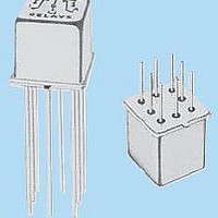
Page 3
... DIMENSIONS ARE SHOWN IN INCHES (MILLIMETERS) ® Established Reliability Relay ER 134 Teledyne Part Numbering System for Military Qualified (JAN) Relays J 134 www.teledynerelays.com SCHEMATIC DIAGRAMS 134 .100 ±.010 (2.54 ±.25) TYP 8 PLACES 134D 134DD SCHEMATICS ARE VIEWED FROM TERMINALS Q= Solder-Coated Leads ...
Page 4
... Dimensions are in inches (mm). 4. Unless otherwise speci¿ ed, tolerance is ± .010 (.25). 5. Add the contact resistance show in the datasheet. 6. Add 0.01 oz. (0. the weight of the relay assembly shown in the datasheet. © 2008 Teledyne Relays Appendix A: Spacer Pads Height For use with the following: ...
Page 5
... Dim H MAX .014 [0.36] (REF) .370 [9.4] MIN +44 (0) 1236 453124 • www.teledyne-europe.com For use with the following: ER411T, J411T, ER412, ER412D ER412DD, J412, J412D, J412DD ER412T, J412T 712, 712D, 712TN ER431T, J431T, ER432, ER432D ER432DD, J432, J432D, J432DD ER432T, J432T ...
Page 6
... Centigrid® Relays: RF180, ER116C, 122C, ER136C Indicates ground pin position Indicates glass insulated lead position Indicates ground pin or lead position depending on relay type © 2008 Teledyne Relays "Z" POSITION "X" POSITION "Y" POSITION TO-5 Relays: ER411, ER431, RF311, RF331 " ...