GRF342-12 TELEDYNE, GRF342-12 Datasheet - Page 3
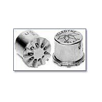
GRF342-12
Manufacturer Part Number
GRF342-12
Description
RF (Radio Frequency) Relays 12V DC-6GHz .15W
Manufacturer
TELEDYNE
Series
GRF342r
Datasheet
1.GRF342-12.pdf
(6 pages)
Specifications of GRF342-12
Coil Current
0.15 W
Frequency
6 GHz
Contact Form
2 Form C (DPDT)
Coil Voltage
12 VDC
Power Consumption
288 mW
Termination Style
PCB
Lead Free Status / RoHS Status
Lead free / RoHS Compliant


GRF342 Page 3
DETAILED ELECTRICAL SPECIFICATIONS
GENERAL NOTES
1. Relays will exhibit no contact chatter in
2. Unless otherwise specified, parameters
3. For extended contact life ratings,
4. Contacts shown in position resulting
5. Relays may be subjected to 260°C,
6. Butt-lead ends are coplanar within
7. Application notes available for PCB
SERIES GRF342
GENERAL ELECTRICAL SPECIFICATIONS
Coil Voltage, Nominal (Vdc)
Coil Resistance (Ohms ±20% @25°C) (Note 4)
Set & Reset Voltage (Vdc, Max.) Pulse Operated
Contact Arrangement
Rated Duty
Contact Resistance
Contact Load Ratings (DC)
Contact Life Ratings
Coil Operating Power
Operate Time
Minimum Operate Pulse
Intercontact Capacitance
Insulation Resistance
Dielectric Strength
excess of 10 µsec or transfer in excess
of 1 µsec.
are initial values.
contact factory.
when Coil A last energized.
peak solder reflow temperature, 1
minute, 3 passes.
.003" (0.08).
layout and mounting information.
SPECIFICATIONS ARE SUBJECT TO CHANGE WITHOUT NOTICE
2 Form C (DPDT)
Continuous
0.15 ohm initial
Resistive:
Low Level:
10,000,000 cycles (typical) at low level
100,000 cycles min. at all other loads specified above
GRF342-5: 410mW typical at nominal rated voltage
GRF342-12: 288mW typical at nominal rated voltage
2.0 ms max at nominal rated coil voltage
6.0 ms @ rated voltage
0.4 pf typical
1,000 megohms min. between mutually isolated terminals
Atmospheric pressure: 350 Vrms/60Hz
BASE PART
NUMBERS
Nom.
Max.
1 Amp/28Vdc
10 to 50 µA/10 to 50mV
OUTLINE DIMENSIONS
.320 MAX
(5.08 ±0.25)
(@25°C) (General Note 2)
(@25°C) (General Note 2)
.200 ±.010
1. DIMENSIONS ARE IN INCHES. METRIC EQUIVALENTS IN MILLIMETERS ARE SHOWN IN ( ).
2. FOR BEST RF PERFORMANCE, SOLDER BOTTOM OF RF GROUND SHIELD TO PCB RF GROUND PLANE.
(8.13)
NOTES:
.031 (.79)
DIA.
www.teledynerelays.com
REF
Ø.375 MAX
(9.53)
GRF342-5
RF GROUND SHIELD
SEE NOTE 2
36° ±3° TYP
5.0
6.0
3.5
.035 (.89)
61
REF
.033 (0.84) REF
(SHOWN: COIL A LAST ENERGIZED CONDITION)
LENGTH
PIN NUMBERS ARE FOR REFERENCE ONLY,
8
7
.335 MAX
9+
6
(8.51)
SCHEMATIC - TERMINAL VIEW
COIL B
10 LEADS
NOT MARKED ON RELAY
5
–
COIL A
10
©2003 TELEDYNE RELAYS
–
(0.43)
.017
+4
1
GRF342-12
DIA.
2
3
+.002
+0.05
-.001
-0.03
12.0
16.0
500
9.0
GRF342/0703/Q1
.035 REF
(.89)
Related parts for GRF342-12
Image
Part Number
Description
Manufacturer
Datasheet
Request
R

Part Number:
Description:
RF (Radio Frequency) Relays 5V DC-6GHz .15W
Manufacturer:
TELEDYNE
Datasheet:

Part Number:
Description:
Relay; E-Mech; Freq (RF); DPDT; Cur-Rtg 1A; Ctrl-V 5DC; Vol-Rtg 28DC; PCB Mnt; 10 Pin
Manufacturer:
TELEDYNE
Datasheet:
Part Number:
Description:
Module; Thru Hole; Solid-State; 3.5 mA @ 115 V (RMS), 3.0 mA @ 220 V (RMS); 7
Manufacturer:
TELEDYNE
Datasheet:
Part Number:
Description:
Module; Thru Hole; Solid-State; 15 mA (Max.); 3.8 to 16 V (RMS); 3 VDC (Min.)
Manufacturer:
TELEDYNE
Datasheet:
Part Number:
Description:
Relay; Hybrid; Freq (RF); DPDT; Cur-Rtg 1A; Ctrl-V 12DC; Vol-Rtg 28DC; PCB Mnt
Manufacturer:
TELEDYNE
Datasheet: