A150-20-5 TELEDYNE, A150-20-5 Datasheet - Page 5
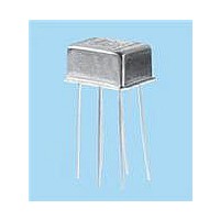
A150-20-5
Manufacturer Part Number
A150-20-5
Description
RF (Radio Frequency) Relays 5VDC 50 ohm
Manufacturer
TELEDYNE
Series
A150r
Datasheet
1.A150-20-5.pdf
(8 pages)
Specifications of A150-20-5
Coil Resistance
50 Ohms
Frequency
3 GHz
Coil Voltage
5 VDC
Power Consumption
1 W
Lead Free Status / RoHS Status
Lead free / RoHS Compliant
Other names
A150-20-5/G


A150 Page 5
SERIES A150
GENERAL PERFORMANCE (–55°C TO +85°C)
ELECTRICAL SPECIFICATION (–55°C TO +85°C, unless otherwise specified)
PARAMETER
Operating Frequency (Note 2)
Power (Notes 5 and 6)
Impedance
PART NUMBER (Note 7)
Coil Voltage Vdc (Note 6)
Coil Resistance Ohms ±20%
Pick-up Voltage Vdc Max.
Switching Time ms (Note 8)
Insulation Resistance
Dielectric strength
PARAMETER
Contact life rating
OUTLINE DIMENSIONS
CASE DETAIL
(
.017
Dimensions are show in inches (millimeters).
Terminal numbers shown are for reference only.
Leads 1 and 7 are grounded to the case.
.43
+.002
–.001
+.05
–.03
)
DIA.
.031 REF.
(.79)
.335 MAX.
(8.51)
2
1
3
.375 MAX.
(9.53)
6
7
5
.700 MIN.
(17.78)
(7.11)
.280
.150 ±.10 TYP.
(5.08 ±5.08)
(3.81 ±.25)
.200 ±.01
SPECIFICATIONS ARE SUBJECT TO CHANGE WITHOUT NOTICE
.035 REF.
(.89)
.435 MAX.
.475 MAX.
(11.05)
(12.07)
@25°C
@25°C
Nom.
Max.
Max.
Typ.
MINIMUM
www.teledynerelays.com
0.0
A150-dB-5
GENERAL NOTES:
1. Contacts will exhibit no contact chatter in excess of 10 μs or
2. Relays may be operated at higher frequencies with reduced RF
3. For optimal RF performance, solder case to RF ground plane.
4. Attenuation values shown are with reference to the through path
5. Power handling for case temperatures of –55°C to +55°C is
6. Do not operate coil at maximum coil voltage continuously.
7. Insert attenuation value, see part numbering system.
8. Switching time includes bounce.
9. The slash and characters appearing after the slash are not
10. Unless otherwise specified, relays will be supplied with either
designator
TELEDYNE RELAYS PART NUMBERING SYSTEM
FOR A150 ATTENUATOR RELAYS
A150
Series
transfer in excess of 1 μs.
performance.
(low loss state).
1 Watt. Derate power handling 25 mW/°C above +55°C. Case
measurement point is adjacent to the relay tab.
marked on the relay.
gold-plated or solder-coated leads.
5.8
3.8
50
5
1,000 MΩ typical (all mutually isolated points)
–
TYPICAL
Attenuation
value (dB)
300 VRMS / 60 Hz typical (at sea level)
XX
50
Typical at low level
A150-dB-12
10,000,000 cycles
16.0
–
390
9.0
12
Nominal coil
voltage
XX
4.0
2.0
MAXIMUM
/
S=.187" leads
See Note 9
A150-dB-15
3.0
1.0
S
20.0
11.3
610
15
©2003 TELEDYNE RELAYS
Q
Q=Solder-Coated Leads
G=Gold-Plated Leads
(Notes 9 & 10)
A150-dB-26
UNITS
Ohms
GHz
Watt
1,560
26.5
32.0
18.0
A150/1203/Q1
Related parts for A150-20-5
Image
Part Number
Description
Manufacturer
Datasheet
Request
R

Part Number:
Description:
Electromechanical Relay 5VDC 50Ohm Through Hole
Manufacturer:
TELEDYNE
Datasheet:
Part Number:
Description:
Electromechanical Relay 5VDC 50Ohm Through Hole
Manufacturer:
TELEDYNE
Datasheet:
Part Number:
Description:
Relay; E-Mech; Freq (RF); DPDT; Cur-Rtg 1A; Ctrl-V 5DC; Vol-Rtg 28DC; PCB Mnt; 10 Pin
Manufacturer:
TELEDYNE
Datasheet:
Part Number:
Description:
Module; Thru Hole; Solid-State; 3.5 mA @ 115 V (RMS), 3.0 mA @ 220 V (RMS); 7
Manufacturer:
TELEDYNE
Datasheet: